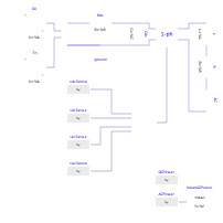
modelPVInverter1phSynch

Grid-tied 1-phase closed-loop inverter with PV source

Extends from Modelica.Icons.Example (Icon for runnable examples).

Information

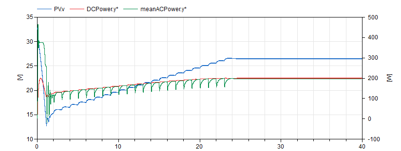
This example represents a simple yet complete grid-tied PV inverter system. A long simulation is performed so as to visualize the time evolution of the MPPT control, which is necessarily much slower than the output current control. This long simulation time is manageable because an averaged switch model is being used, which means that the simulation can have longer time steps.

This evolution can be observed by plotting the DC bus voltage as well as the input and output power to the inverter:
PVInverter1phSynchResultsA.png

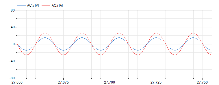
As expected, the power factor of the output power is 1 (all active power), having the output current in synch with the grid voltage:
PVInverter1phSynchResultsB.png

Components

TypeNameDefaultDescription
Electrical.PVArrayPV
Modelica.Blocks.Sources.ConstantGn
Modelica.Blocks.Sources.ConstantTn
PVSystems.Electrical.Assemblies.HBridgeInverter
Modelica.Electrical.Analog.Sources.SineVoltageAC
Modelica.Electrical.Analog.Basic.InductorL
Modelica.Electrical.Analog.Basic.ResistorR
Modelica.Electrical.Analog.Basic.CapacitorCdc
Control.Assemblies.Inverter1phCompleteControllerController
Modelica.Electrical.Analog.Basic.ResistorRdc
Modelica.Electrical.Analog.Basic.Groundground
Modelica.Blocks.Sources.RealExpressionvdcSense
Modelica.Blocks.Sources.RealExpressionidcSense
Modelica.Blocks.Sources.RealExpressioniacSense
Modelica.Blocks.Sources.RealExpressionvacSense
Modelica.Blocks.Sources.RealExpressionDCPower
Modelica.Blocks.Sources.RealExpressionACPower
Modelica.Blocks.Math.MeanmeanACPower