This example presents a circuit composed of a resistor in series with a sinusoidal AC voltage source and the ideal current bidirectional switch. The switch is operated by a step block that changes from 0 to 1 in the middle of the simulation. This changes the state of the switch from open to closed.
To use the example, simulate the model as provided and plot the source voltage as well as the switch voltage, the plot should look like this:
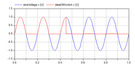
Notice how at the begining of the simulation, when the switch is not closed, it blocks all the positive voltage, preventing current from flowing. On the other hand, the negative voltage is not blocked, so the current can flow (through the anti-parallel diode). When the switch is closed using the firing signal, it never blocks voltage, allowing bidirectional flow of current.
Plot the voltage drop in the resistor to confirm these results or play with the parameter values to see what effects they have.