This model provides a changing duty cycle with the use of two step blocks. When running the simulation with the provided values, plotting the fire output generates the following graph:
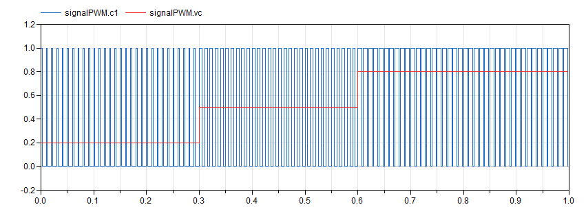
Through inspection of the plot, it can be seen how the signal constitutes a PWM signal with a duty cycle changing in steps through the values 0.2, 0.5 and 0.8. Zoom into the signal to confirm this fact as well as the value of the period, set at 10 milliseconds.