modelGovHydro4Base
Base class for Governors of hydraulic turbines
Information
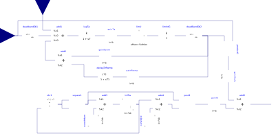
This base model implements a control diagram wich can be specialized in governors for hydraulic turbines.The upper part of the diagram implements the frequency primary regulation and the dynamic of the gates servomotor; the lower part completes the turbine model.
The caracteristic function of the turbine is omitted, because it depends on the turbine type (Pelton-Francis-Kaplan). Said characteristic shall connect the deadBandDb2 output to the input u1 of the div1 block, and shall be implemented in the specialized class.
In the specialized class can be also implemented additional inputs, if needed.
The caracteristic function describes the relationship of flow through the turbine to stroke of the gate actuating servomotor.
This curve is proportional to turbine power, with the constant of proportionality being a function of available head. This constant must be specified by the turbine gain At.
The typical value of At is slightly greater than unity while the typical range of Qnl is 0 - 0.15.
Parameters
| Type | Name | Default | Description |
|---|---|---|---|
| Control and Actuators | |||
| Modelica.SIunits.PerUnit | db1 | 0 | Intentional dead-band width |
| Modelica.SIunits.PerUnit | db2 | 0 | Unintentional dead-band width |
| Modelica.SIunits.Time | Tp | 0.1 | Pilot servo time constant |
| Modelica.SIunits.Time | Tg | 0.5 | Gate servo time constant |
| Modelica.SIunits.Time | Tr | 5 | Dashpot time constant |
| Modelica.SIunits.PerUnit | uo | 0.2 | Max gate opening velocity |
| Modelica.SIunits.PerUnit | uc | -0.2 | Max gate closing velocity |
| Modelica.SIunits.PerUnit | gMax | 1 | Maximum gate opening |
| Modelica.SIunits.PerUnit | gMin | 0 | Minimum gate opening |
| Modelica.SIunits.PerUnit | rPerm | 0.05 | Permanent droop |
| Modelica.SIunits.PerUnit | rTemp | 0.3 | Temporary droop |
| Turbine | |||
| Real[:,:] | GvPgvTable | [0, 0; 1, 1] | Points to define the curve Pgv = f(Gv) |
| Modelica.Blocks.Types.Smoothness | GvPgvSmoothness | Modelica.Blocks.Types.Smoothness.LinearSegments | Smoothness of curve Pgv = f(Gv) |
| Modelica.SIunits.PerUnit | at | 1.2 | Turbine gain |
| Modelica.SIunits.PerUnit | qnl | 0.08 | No-load flow at nominal head |
| Modelica.SIunits.Time | Tw | 1 | Water inertia time constant |
| Modelica.SIunits.PerUnit | hDam | 1 | Head available at dam |
| Modelica.SIunits.PerUnit | dTurb | 0.5 | Turbine damping factor |
| Initialization | |||
| Modelica.SIunits.PerUnit | qStart | Turbine flow Start value | |
Connectors
| Type | Name | Default | Description |
|---|---|---|---|
| Modelica.Blocks.Interfaces.RealInput | deltaOmegaPu | ||
| Modelica.Blocks.Interfaces.RealInput | PrefPu | ||
| Modelica.Blocks.Interfaces.RealOutput | PmPu |
Components
| Type | Name | Default | Description |
|---|---|---|---|
| PowerGrids.Controls.DiscontinuousDeadBand | deadbandDb1 | ||
| Modelica.Blocks.Math.Add3 | add1 | ||
| PowerGrids.Controls.FirstOrder | lagTp | ||
| Modelica.Blocks.Nonlinear.Limiter | limU | ||
| PowerGrids.Controls.IntegratorWithNonWindupLimiter | limIntG | ||
| Modelica.Blocks.Math.Add | add2 | ||
| Modelica.Blocks.Math.Gain | gainRperm | ||
| PowerGrids.Controls.DerivativeLag | derlagTrRtemp | ||
| Modelica.Blocks.Math.Division | div1 | ||
| Modelica.Blocks.Math.Product | square1 | ||
| Modelica.Blocks.Sources.Constant | constHdam | ||
| Modelica.Blocks.Sources.Constant | constQnl | ||
| Modelica.Blocks.Math.Product | prod1 | ||
| Modelica.Blocks.Math.Gain | gainAt | ||
| Modelica.Blocks.Math.Add | add3 | ||
| Modelica.Blocks.Math.Add | add4 | ||
| Modelica.Blocks.Math.Add | add5 | ||
| Modelica.Blocks.Math.Gain | gainDturb | ||
| Modelica.Blocks.Math.Product | product1 | ||
| Modelica.Blocks.Math.Gain | gainTg | ||
| Modelica.Blocks.Math.Gain | gainRtemp | ||
| Modelica.Blocks.Continuous.Integrator | intTw | ||
| PowerGrids.Controls.DeadBand | deadBandDb2 |