This model demonstrates the correct
behaviour of a tap-changer logic of type
INTERVAL by directly
prescribing the moniitoring
conditions valueUnderMin, valueAboveMax.
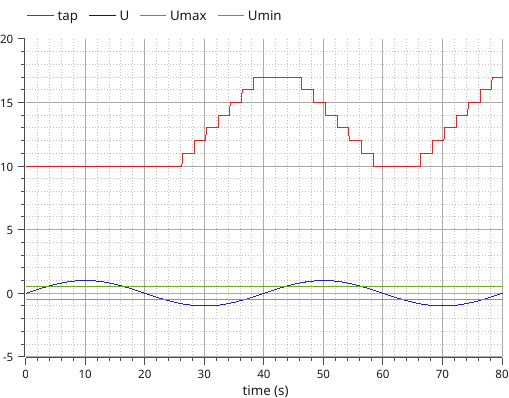
The logic starts with tap changer in position 5.
The monitored value U is a sine wave and does not depend from
the tap position. The monitoring INTERVAL is [-0.5, 0.5].
The Locked signal is active in t = [0, 20] interval.
The tap position stays frozen until t=20, because the locked
signal is active.
After the Locked signal disappears, the tap position starts to
move according to the defined time lag intervals (3 second for
first tap, 2 second for subsequent taps) and to the actual value of
U (tap position increases when U is higher than 0.5, and decreases
when U is lower than -0.5).