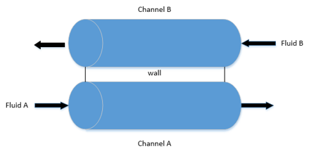
Countercurrent heat exchanger model consist of two channels A and B, and a separating heat transfer wall in between. Fluids A and B are flowing in the channels A and B respectively. Heat exchanger is assumed to be insulated around the outside, therefore, heat transfer occurs just between the fluids A and B. Fluid B is considered as the hot fluid and fluid A is considered to be the cold fluid.
Heat exchanger mass balance equations for the fluids can be written as:

where ρ is the density of the fluid, A is the cross section and w is the mass flow rate. Density and the cross section are assumed to be constant for the fluids, hence mass flow rate is considered constant along the channels.
Heat exchanger energy balance equations are described considering a small portion l=L/(N-1) on the channels where L is the length of each channel, and N is the number of nodes on the channels. Therefore, N-1 corresponds to the number of channel and wall segments. And, there are N-1 heat flow rates and N-1 temperature variables for the wall which are considered for the segments. Discretized energy balance equations for the countercurrent heat exchanger are described as:
for j=1…N-1 where A_A and A_B are the cross section areas of the channels, ρ_A and ρ_B are the densities, c_pA and c_pB are the specific heat capacities, w_A and w_B are the mass flow rates of the fluids A and B respectively. Moreover, T_A and T_B are the temperature variables of the fluids A and B respectively, entering and exiting the small portion l. And, Q_A is the heat flow rate from wall to channel A, and Q_B is the heat flow rate from channel B to wall. In addition to this, boundary conditions were defined for the first node for T_A and for the node N for T_B.
The wall between the channels is assumed to be very thin, so its thermal resistance is neglected. Heat transfer occurs from the fluid A in channel A to the wall and from the wall to the fluid B in channel B. Energy balance at the each wall segment:

for j=1…N-1 where γ_A and γ_B are the heat transfer coefficients of fluids A and B respectively, and ω_A and ω_B are the perimeter of the channels A and B respectively. Moreover, c_w is the specific heat capacity of the wall and T_w is the temperature variable of the wall segment. Parameters in the CounterCurrentHeatExchangerEquations:
| Parameters | Comment |
|---|---|
| L | length |
| N | number of nodes |
| wB | mass flow rate of B |
| areaA | cross sectional area of A |
| areaB | cross sectional area of B |
| rhoA | density of A |
| rhoB | density of B |
| cpA | specific heat capacity of A |
| cpB | specific heat capacity of B |
| cpW | specific heat capacity of the wall |
| gammaA | heat transfer coefficient of A |
| gammaB | heat transfer coefficient of B |
| omega | perimeter |
| l | length of each wall segment |