classIdealHBridge
Ideal H-Bridge
Extends from Servomechanisms.Utilities.box, Servomechanisms.Utilities.IconNameB.
Information
General
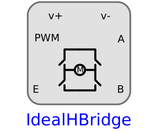
This component simulates the behaviour of an h-bridge using ideal switches.
Implementation
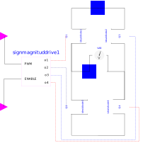
This model has 4 ideal switches Q1, Q2, Q3 and Q4 wich their respective diode.
Q1 and Q4 form half bridge and Q2 and Q3 the other half bridge.
The bridge is controlled using a Sign-Magnitude drive with
boolean inputs and outputs.
Notes
- The voltage should be applied on the electrical interfaces (Vpos and Vneg) using an external dc source for example DCSource .
- It uses the Sign-Magnitude method to control the signal SignMagnitudDrive .
- The motor pins should be connected to the MotorA and MotorB pins.
- The inputs are the logical inputs PWM and ENABLE (or direction), which can be generated by an external element, for example Controller .
- This model has a voltage sensor (real value) between MotorA and MotorB pins and
- Ron (switch resistance when ON) and Goff (swithch conductance when OFF) can be zero.
See also
Parameters
| Type | Name | Default | Description |
|---|---|---|---|
| SI.Resistance | Ron | 0 | Closed switch resistance |
| SI.Conductance | Goff | 0 | Opened switch conductance |