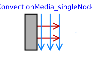
modelConvectionMedia_singleNode
Information
This is a model of linear heat convection, e.g., the heat transfer between a plate and the surrounding air; see also: ConvectiveResistor. It may be used for complicated solid geometries and fluid flow over the solid by determining the convective thermal conductance Gc by measurements. The basic constitutive equation for convection is
   Q_flow = Gc*(solid.T - fluid.T);
   Q_flow: Heat flow rate from connector 'solid' (e.g., a plate)
      to connector 'fluid' (e.g., the surrounding air)
Gc = G.signal[1] is an input signal to the component, since Gc is nearly never constant in practice. For example, Gc may be a function of the speed of a cooling fan. For simple situations, Gc may be calculated according to
   Gc = A*h
   A: Convection area (e.g., perimeter*length of a box)
   h: Heat transfer coefficient
where the heat transfer coefficient h is calculated from properties of the fluid flowing over the solid. Examples:
Machines cooled by air (empirical, very rough approximation according to R. Fischer: Elektrische Maschinen, 10th edition, Hanser-Verlag 1999, p. 378):
    h = 7.8*v^0.78 [W/(m2.K)] (forced convection)
      = 12         [W/(m2.K)] (free convection)
    where
      v: Air velocity in [m/s]
Laminar flow with constant velocity of a fluid along a flat plate where the heat flow rate from the plate to the fluid (= solid.Q_flow) is kept constant (according to J.P.Holman: Heat Transfer, 8th edition, McGraw-Hill, 1997, p.270):
   h  = Nu*k/x;
   Nu = 0.453*Re^(1/2)*Pr^(1/3);
   where
      h  : Heat transfer coefficient
      Nu : = h*x/k       (Nusselt number)
      Re : = v*x*rho/mue (Reynolds number)
      Pr : = cp*mue/k    (Prandtl number)
      v  : Absolute velocity of fluid
      x  : distance from leading edge of flat plate
      rho: density of fluid (material constant
      mue: dynamic viscosity of fluid (material constant)
      cp : specific heat capacity of fluid (material constant)
      k  : thermal conductivity of fluid (material constant)
   and the equation for h holds, provided
      Re < 5e5 and 0.6 < Pr < 50
Connectors
| Type | Name | Default | Description |
|---|---|---|---|
| Interfaces.HeatPort_Flow | port_a | ||
| Interfaces.HeatPort_Flow | port_b |
Components
| Type | Name | Default | Description |
|---|---|---|---|
| SI.Pressure | p | 1e5 | Pressure at port_b or specify state |
| Modelica.Media.Air.MoistAir.ThermodynamicState | state | Medium.setState_pTX(p, port_b.T) | Thermodynamic state of fluid at port_b |
| SI.Velocity | v | Specify velocity or m_flow | |
| SI.MassFlowRate | m_flow | Medium.density(state)*crossArea*v | Mass flow rate |
| SI.Diameter | dimension | 4*crossArea/perimeter | Characteristic dimension (e.g. hydraulic diameter) |
| SI.Area | crossArea | 0.25*pi*dimension^2 | Cross sectional flow area |
| SI.Length | perimeter | pi*dimension | Wetted perimeter |
| SI.Length | dlength | 1 | Characteristic length of heat transfer segment |
| SI.Area | surfaceArea | dimension*dlength | Surface area for heat transfer |
| SI.Height | roughness | 2.5e-5 | Average height of surface asperities |
| HeatTransferCoeff | heatTransferCoeff | ||
| SI.CoefficientOfHeatTransfer | alpha | heatTransferCoeff.alphas[1] | |
| SI.HeatFlowRate | Q_flow | Heat flow rate from solid -> fluid | |
| SI.TemperatureDifference | dT | = port_a.T - port_b.T | |
| SI.ThermalResistance | R | Thermal resistance |
Contents
| Name | Description |
|---|---|
 Medium | |
 HeatTransferCoeff |