
modelCell1Dim
Information
Model Cell1Dim describes the flow of fluid through a single cell. An overall flow model can be obtained by interconnecting several cells in series (see Flow1Dim).
Pressure and enthalpy are selected as state variables.
Two types of variables can be distinguished: cell variables and node variables. Node variables are characterized by the su (supply) and ex (exhaust) subscripts, and correspond to the inlet and outlet nodes at each cell. The relation between the cell and node values depends on the discretization scheme selected.
The assumptions for this model are:
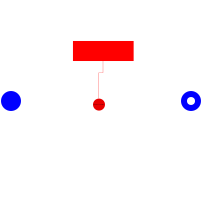
The model is characterized by two flow connector and one lumped thermal port connector. During normal operation the fluid enters the model from the InFlow connector and exits from the OutFlow connector. In case of flow reversal the fluid direction is inversed.
The thermal energy transfer through the lateral surface is computed by the ConvectiveHeatTransfer model which is inerithed in the Cell1Dim model.
Modelling options
In the General tab the following options are availabe:
In the Initialization tab the following options are availabe:
Numerical options
In this tab several options are available to make the model more robust:
Parameters
| Type | Name | Default | Description |
|---|---|---|---|
| Integer | Nt | 1 | Number of cells in parallel |
| Real | pi | Modelica.Constants.pi | pi-greco |
| Modelica.SIunits.Volume | Vi | Volume of a single cell | |
| Modelica.SIunits.Area | Ai | Lateral surface of a single cell | |
| Modelica.SIunits.MassFlowRate | Mdotnom | Nominal fluid flow rate | |
| Modelica.SIunits.CoefficientOfHeatTransfer | Unom_l | if HTtype = LiqVap : Heat transfer coefficient, liquid zone | |
| Modelica.SIunits.CoefficientOfHeatTransfer | Unom_tp | if HTtype = LiqVap : heat transfer coefficient, two-phase zone | |
| Modelica.SIunits.CoefficientOfHeatTransfer | Unom_v | if HTtype = LiqVap : heat transfer coefficient, vapor zone | |
| Initialization | |||
| Modelica.SIunits.Pressure | pstart | Fluid pressure start value | |
| Medium.SpecificEnthalpy | hstart | 1E5 | Start value of enthalpy |
| Numerical options | |||
| Discretizations | Discretization | ThermoCycle.Functions.Enumerations.Discretizations.centr_diff | Selection of the spatial discretization scheme |
| Boolean | Mdotconst | false | Set to yes to assume constant mass flow rate at each node (easier convergence) |
| Boolean | max_der | false | Set to yes to limit the density derivative during phase transitions |
| Boolean | filter_dMdt | false | Set to yes to filter dMdt with a first-order filter |
| Real | max_drhodt | 100 | Maximum value for the density derivative |
| Modelica.SIunits.Time | TT | 1 | Integration time of the first-order filter |
| Boolean | ComputeSat | false | Can be disabled if the flow is single-phase, or if saturation is passed as a parameter |
| Initialization › Intialization options | |||
| Boolean | steadystate | true | if true, sets the derivative of h (working fluids enthalpy in each cell) to zero during Initialization |
Connectors
| Type | Name | Default | Description |
|---|---|---|---|
| ThermoCycle.Interfaces.Fluid.FlangeA | InFlow | ||
| ThermoCycle.Interfaces.Fluid.FlangeB | OutFlow | ||
| ThermoCycle.Interfaces.HeatTransfer.ThermalPortL | Wall_int |
Components
| Type | Name | Default | Description |
|---|---|---|---|
| Real | sat_in | {0, 0, 0, 0, 0, 0, 1E5, 0, 0, 0, 0, 0, 0, 300} | |
| HeatTransfer | heatTransfer | ||
| Medium.ThermodynamicState | fluidState | ||
| Medium.SaturationProperties | sat | ||
| Medium.AbsolutePressure | p | ||
| Modelica.SIunits.MassFlowRate | M_dot_su | ||
| Modelica.SIunits.MassFlowRate | M_dot_ex | ||
| Medium.SpecificEnthalpy | h | Fluid specific enthalpy at the cells | |
| Medium.Temperature | T | Fluid temperature | |
| Medium.Density | rho | Fluid cell density | |
| Modelica.SIunits.DerDensityByEnthalpy | drdh | Derivative of density by enthalpy | |
| Modelica.SIunits.DerDensityByPressure | drdp | Derivative of density by pressure | |
| Modelica.SIunits.SpecificEnthalpy | hnode_su | Enthalpy state variable at inlet node | |
| Modelica.SIunits.SpecificEnthalpy | hnode_ex | Enthalpy state variable at outlet node | |
| Real | dMdt | Time derivative of mass in cell | |
| Modelica.SIunits.HeatFlux | qdot | heat flux at each cell | |
| Real | x | Vapor quality | |
| Modelica.SIunits.SpecificEnthalpy | h_l | ||
| Modelica.SIunits.SpecificEnthalpy | h_v | ||
| Modelica.SIunits.Power | Q_tot | Total heat flux exchanged by the thermal port | |
| Modelica.SIunits.Mass | M_tot | Total mass of the fluid in the component |
Contents
| Name | Description |
|---|---|
| Medium | |
 HeatTransfer HeatTransfer |