Information
## Copyright © EDF 2002 - 2026
## ThermoSysPro Version 4.2
This component model is documented in Sect. 9.7.1 of the ThermoSysPro book.
# Static condenser
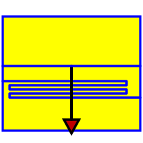
This condenser is a large shell-and-tube heat exchanger. It is composed of a bundle of circular tubes mounted in a cavity. The steam in the cavity condensates due to the cooling water flow in the tube bundle. The condenser is positioned at the outlet of the steam turbine in order to receive a large flow rate of low-pressure steam. The steam condensation heat is evacuated by external cooling water pumped through the condenser tube bundle. The condensate at the outlet is pumped and sent into feed water heaters.
Following assumptions are made in the model:
- the efficiency of the condenser is equal to 1 (all the steam is condensed).
- the energy accumulation in the wall is neglected.
- the hot fluid is assumed to stay at saturation temperature in the condensation zone (no desuperheating zone and no subcooled zone).
The latter assumption is valid when the condenser is under normal operating conditions: the steam coming from the turbine and the outgoing condensate are at saturation temperature. When superheated steam is directly sent to the condenser, the [dynamic condenser model](modelica://ThermoSysPro.WaterSteam.HeatExchangers.DynamicCondenser) is more appropriate.
## Modelica component model
The equations mentioned below are implemented in the component *StaticCondenser*, located in the *WaterSteam.HeatExchangers* sub-library.
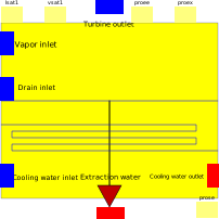
This component has 6 connectors:
- Cee: cooling water inlet,
- Cse: cooling water outlet,
- Cex: extraction water outlet,
- Cvt: turbine outlet, employed as inlet,
- Cep: drain inlet,
- Cev: vapor outlet.

## Nomenclature
| Symbol| Description| Unit| Definition| Modelica name |
| :----------------------------------- | :------------------------------------------------------------------------------------------- | :------------------------------------------- | :---------------------------------------------------------------------- | :----------- |
| \\(A\\)| Heat exchange surface| \\(\mathrm{m}^{2}\\)|| SCO |
| \\(C\\)| Fouling coefficient| \\(-\\)|| COP |
| \\(C\_{\text {ref }}\\)| Reference fouling coefficient| \\(-\\)|| COPR |
| \\(h\_{\mathrm{c}, \mathrm{i}}\\)| Cold fluid specific enthalpy at the inlet| \\(\mathrm{J} / \mathrm{kg}\\)|| Cee.h |
| \\(h\_{\mathrm{c}, \mathrm{o}}\\)| Cold fluid specific enthalpy at the outlet| \\(\mathrm{J} / \mathrm{kg}\\)|| Cse.h |
| \\(h\_{\mathrm{d}, \mathrm{i}}\\)| Specific enthalpy at the inlet \(from drain\)| \\(\mathrm{J} / \mathrm{kg}\\)|| Cep.h |
| \\(h^{\mathrm{h}}\\)| Hot fluids mixing specific enthalpy| \\(\mathrm{J} / \mathrm{kg}\\)|| Hmv |
| \\(h\_{l,0}\\)| Liquid specific enthalpy at the outlet of the condenser \(drain\)| \\(\mathrm{J} / \mathrm{kg}\\)| \\(h\_{l}^{\mathrm{sat}}+\frac{\left\(P\_{\mathrm{b}}-P\right\)}{\rho\_{l}}\\) | Cex.h |
| \\(h\_{l}^{\text {sat }}\\)| Hot fluid saturation enthalpy of the liquid| \\(\mathrm{J} / \mathrm{kg}\\)|| lsat1.h |
| \\(h\_{\mathrm{t}, \mathrm{i}}\\)| Specific enthalpy of the steam coming from the turbine| \\(\mathrm{J} / \mathrm{kg}\\)|| Cvt.h |
| \\(h\_{\mathrm{v}, \mathrm{i}}\\)| Specific enthalpy of the steam coming from the boiler outlet or from the turbine inlet valve | \\(\mathrm{J} / \mathrm{kg}\\)|| Cev.h |
| \\(h\_{\text {cond }}\\)| Heat exchange coefficient: correlation given by the manufacturers| \\(\mathrm{W} / \mathrm{m}^{2} / \mathrm{K}\\) || XKCO |
| \\(K\_{\text {cond }}\\)| Reference heat exchange coefficient| \\(\mathrm{W} / \mathrm{m}^{2} / \mathrm{K}\\) || KCO |
| \\(m\_{\mathrm{c}}\\)| Cold fluid \(water\) mass flow rate| \\(\mathrm{kg} / \mathrm{s}\\)|| Cee.Q |
| \\(m\_{\mathrm{c}, \mathrm{ref}}\\)| Cold fluid \(water\) reference mass flow rate| \\(\mathrm{kg} / \mathrm{s}\\)|| QC0 |
| \\(\dot{m}\_{\mathrm{d}, \mathrm{i}}\\) | Water mass flow rate at the inlet \(drain\)| \\(\mathrm{kg} / \mathrm{s}\\)|| Cep.Q |
| \\(\dot{m}\_{\mathrm{d}, \mathrm{o}}\\) | Water mass flow rate at the outlet of the condenser| \\(\mathrm{kg} / \mathrm{s}\\)|| Cex.Q |
| \\(m\_{\mathrm{t}, \mathrm{i}}\\)| Mass flow rate of the steam coming from the turbine| \\(\mathrm{kg} / \mathrm{s}\\)|| Cvt.Q |
| \\(m\_{\mathrm{v}, \mathrm{i}}\\)| Mass flow rate of the steam coming from the boiler outlet or from the turbine inlet valve| \\(\mathrm{kg} / \mathrm{s}\\)|| Cev.Q |
| \\(P\\)| Steam pressure inside the condenser \(cavity pressure\)| \\(\mathrm{Pa}\\)|| Pcond |
| \\(P\_{\mathrm{b}}\\)| Fluid pressure at the bottom of the cavity \(drain outlet\)| \\(\mathrm{Pa}\\)| \\(P+\rho\_{l} \cdot g \cdot z\_{l}\\)| Cex.P |
| \\(P\_{\mathrm{c}, \mathrm{i}}\\)| Cold fluid pressure at the inlet| \\(\mathrm{Pa}\\)|| Cee.P |
| \\(P\_{\mathrm{c}, \mathrm{o}}\\)| Cold fluid pressure at the outlet| \\(\mathrm{Pa}\\)|| Cse.P |
| \\(T\_{\mathrm{c}, \mathrm{i}}\\)| Cold fluid \(water\) temperature at the inlet| \\(\mathrm{K}\\)|| Tee |
| \\(T\_{\mathrm{c}, \mathrm{o}}\\)| Cold fluid \(water\) temperature at the outlet| \\(\mathrm{K}\\)|| Tse |
| \\(T\_{\mathrm{c}, \text { ref }}\\)| Cold fluid \(water\) reference temperature| \\(\mathrm{K}\\)|| - |
| \\(T^{\text {sat }}\\)| Saturation temperature| \\(\mathrm{K}\\)|| lsat1.T, vsat1.T |
| \\(W\\)| Heat power released to the cold fluid \(thermal power exchanged\)| \\(\mathrm{W}\\)|| W |
| \\(z\_{l}\\)| Water level in the condenser| \\(\mathrm{m}\\)|| z |
| \\(\Delta P\_{\mathrm{c}}\\)| Cold fluid pressure loss between the inlet and the outlet| \\(\mathrm{Pa}\\)| \\(P\_{\mathrm{c}, \mathrm{i}}-P\_{\mathrm{c}, \mathrm{o}}\\)| - |
| \\(\Lambda\_{\mathrm{c}}\\)| Cold fluid friction pressure loss coefficient| \\(\mathrm{m}^{-4}\\)|| CPCE |
| \\(\rho\_{\mathrm{c}}\\)| Cold fluid density| \\(\mathrm{kg} / \mathrm{m}^{3}\\)|| rho_ee |
| \\(\rho\_{l}\\)| Water density at the extraction point \(i.e., at the liquid outlet of the condenser\)| \\(\mathrm{kg} / \mathrm{m}^{3}\\)|| rho_ex |
## Governing equations
### Power received by the cold fluid
- Validity domain:
\\(\forall \dot{m}\_{\mathrm{c}}\\)
- Mathematical formulation:
$$W=\dot{m}\_{\mathrm{c}} \cdot\left\(h\_{\mathrm{c}, \mathrm{o}}-h\_{\mathrm{c}, \mathrm{i}}\right\)$$
- Comments:
### Mass balance equation of the hot fluids
- Validity domain:
\\(\forall \dot{m}\_{t, i}, \forall \dot{m}\_{v, i}\\) and \\(\forall \dot{m}\_{\mathrm{d}, \mathrm{i}}\\)
- Mathematical formulation:
$$\dot{m}\_{\mathrm{d}, \mathrm{o}}=\dot{m}\_{\mathrm{t}, \mathrm{i}}+\dot{m}\_{\mathrm{v}, \mathrm{i}}+\dot{m}\_{\mathrm{d}, \mathrm{i}}$$
- Comments:
There are three sources of hot fluids the turbine, the boiler outlet or turbine inlet valve, and the drain.
### Specific mixing enthalpy of the hot fluids
- Validity domain:
\\(\dot{m}\_{\mathrm{d}, \mathrm{o}} \neq 0, \forall \dot{m}\_{\mathrm{t}, \mathrm{i}}, \forall \dot{m}\_{\mathrm{v}, \mathrm{i}}\\) and \\(\forall \dot{m}\_{\mathrm{d}, \mathrm{i}}\\)
- Mathematical formulation:
$$\dot{m}\_{\mathrm{d}, \mathrm{o}} \cdot h^{\mathrm{h}}=\dot{m}\_{\mathrm{t}, \mathrm{i}} \cdot h\_{\mathrm{t}, \mathrm{i}}+\dot{m}\_{\mathrm{v}, \mathrm{i}} \cdot h\_{\mathrm{v}, \mathrm{i}}+\dot{m}\_{\mathrm{d}, \mathrm{i}} \cdot h\_{\mathrm{d}, \mathrm{i}}$$
- Comments:
The mixing enthalpy is used to compute the properties of the hot fluid inside the condenser
### Energy released during the condensation of the steam at the inlets
- Validity domain:
\\(\forall \dot{m}\_{t, 1}, \forall \dot{m}\_{\mathrm{v}, \mathrm{i}},\\) and \\(\forall \dot{m}\_{\mathrm{d}, \mathrm{i}}\\)
- Mathematical formulation:
$$W=\dot{m}\_{\mathrm{t}, \mathrm{i}} \cdot\left\(h\_{\mathrm{t}, \mathrm{i}}-h\_{l}^{\mathrm{sat}}\right\)\right\)+\dot{m}\_{\mathrm{v}, \mathrm{i}} \cdot\left\(h\_{\mathrm{v}, \mathrm{i}}-h\_{l}^{\mathrm{sat}}\right\) + \dot{m}\_{\mathrm{d}, \mathrm{i}} \cdot \left\(h\_{\mathrm{d}, \mathrm{i}}-h\_{l}^{\mathrm{sat}}\right\)$$
- Comments:
There are three sources of steam the turbine, the boiler outlet or turbine inlet valve, and the drain \(outlets of water heaters for instence\). The steam is assumed completely condensed.
### Power exchanged between the hot and the cold fluids
- Validity domain:
\\(W>0\\)
- Mathematical formulation:
$$T^{\mathrm{sat}}-T\_{\mathrm{c}, \mathrm{o}}=\left\(T^{\mathrm{sat}}-T\_{\mathrm{c}, \mathrm{i}}\right\) \cdot e^{\frac{h\_{\mathrm{cond}} \cdot A \cdot\left\(T\_{\mathrm{c}, \mathrm{i}}-T\_{\mathrm{c}, \mathrm{o}}\right\)}{W}}$$
- Comments:
The hot fluid is assumed to stay at saturation temperature between inlet and outlet of the condenser \(no desuperheating zone and no subcooled zone\).
### Momentum balance equation \(cold fluid\)
- Validity domain:
\\(\forall \dot{m}\_{\mathrm{c}}\\)
- Mathematical formulation:
$$\Delta P\_{\mathrm{c}}=\Lambda\_{\mathrm{c}} \cdot \frac{\dot{m}\_{\mathrm{c}} \cdot\lvert \dot{m}\_{\mathrm{c}}\rvert }{\rho\_{\mathrm{c}}}$$
- Comments:
Only friction pressure losses are taken into account.
## References
El Hefni, Baligh and Bouskela, Daniel (2019). [Modeling and Simulation of Thermal Power Plants with ThermoSysPro](https://link.springer.com/book/10.1007/978-3-030-05105-1), sect. 9.7.1. Springer Nature Switzerland AG.