
modelStep5Splitter
Extends from Modelica.Icons.Example (Icon for runnable examples).
Information
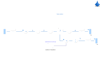
In a fifth step, a splitter is introduced. The bypass flow routed through the valve is commonly used to control the air cycle.
Further documentation is available in the AirCycle package.
Components
| Type | Name | Default | Description |
|---|---|---|---|
| ThermofluidStream.DropOfCommons | dropOfCommons | ||
| ThermofluidStream.Idealized.Processes.Adiabatic | compressor | ||
| ThermofluidStream.Idealized.Processes.Adiabatic | turbine | ||
| ThermofluidStream.Boundaries.Source | airSource | ||
| ThermofluidStream.Idealized.Processes.Isobaric | heatExchangerSideA | ||
| ThermofluidStream.Utilities.showRealValue | coefficientOfPerformance | Warning: COP goes to infinity for compressor.eta= turbine.eta = 1 and dp = 0 (no error of the model). | |
| Boundaries.Sink_free | airSink | ||
| Processes.Isenthalpic | valve | ||
| ThermofluidStream.Topology.SplitterT2 | splitter | ||
| Boundaries.MassFlowRate | massFlowRateValve | ||
| Boundaries.Sink_free | airSink1 | ||
| Modelica.Blocks.Sources.Ramp | massFlowRateValveRamp | ||
| Boundaries.MassFlowRate | massFlowRateIn | ||
| ThermofluidStream.Sensors.SingleFlowSensor | inletEnthalpyFlowRate | ||
| ThermofluidStream.Sensors.SingleFlowSensor | outlet1EnthalpyFlowRate | ||
| ThermofluidStream.Sensors.SingleFlowSensor | outlet2EnthalpyFlowRate |
Contents
| Name | Description |
|---|---|
 Medium Medium |
Revisions
-
2026, by Raphael Gebhart (raphael.gebhart@dlr.de):
Initial version.