
modelStep2VaryingMassFlowRate
Extends from Modelica.Icons.Example (Icon for runnable examples).
Information
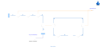
In a second step, energy flow connectors are introduced and the gas turbine mass flow rate is varied with time.
Note that for an air mass flow rate below 1.03 kg/s, the air outlet temperature
(heatExchangerAirSide.outlet.T) falls below the water inlet temperature
(heatExchangerWaterSide.inlet.T). This violates the second law of thermodynamics and
must be avoided, for example by introducing a heat exchanger efficiency.
Further documentation is available in the CombinedCycle package.
Components
| Type | Name | Default | Description |
|---|---|---|---|
| ThermofluidStream.DropOfCommons | dropOfCommons | ||
| ThermofluidStream.Idealized.Processes.Adiabatic | pump | ||
| ThermofluidStream.Idealized.Processes.Adiabatic | turbineCR | ||
| ThermofluidStream.Idealized.Processes.Isobaric | heatExchangerWaterSide | ||
| Boundaries.LoopBreaker_m | loopBreaker | ||
| ThermofluidStream.Idealized.Processes.Isobaric | cooler | ||
| ThermofluidStream.Idealized.Processes.Adiabatic | compressor | ||
| ThermofluidStream.Idealized.Processes.Adiabatic | turbineJB | ||
| ThermofluidStream.Boundaries.Source | airSource | ||
| ThermofluidStream.Idealized.Processes.Isobaric | combustion | ||
| .ThermofluidStream.Boundaries.Sink_m | airSink | ||
| ThermofluidStream.Idealized.Processes.Isobaric | heatExchangerAirSide | ||
| Modelica.Blocks.Sources.Ramp | massFlowRateRamp | ||
| EnergyFlow.Components.Sum | generatorPower | ||
| ThermofluidStream.Utilities.showRealValue | efficiency |
Contents
| Name | Description |
|---|---|
 Water Water | |
 Air Air |
Revisions
-
2026, by Raphael Gebhart (raphael.gebhart@dlr.de):
Initial version.