
modelFan_L1
Information
1. Purpose of model
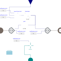
Simple model for electric fan using a polytropic as well as electric and mechanical efficiency.
2. Level of detail, physical effects considered, and physical insight
- The mass flow through the fan is set independendy of the in- and outlet boundary conditions, which is not physical.
- No air control volume is used, and thus there is no momentum, mass or energy storage in the component.
- No backflow is possible.
- The mass flow is ideally controlled.
- Dynamics are modelled as first order system with set point and actual massflow (due to mechanical and control inertia)
3. Limits of validity
- Constant efficiencies are currently used, but may be replaced with performance tables.
4. Interfaces
- Air Inlet
- Air Outlet
- Mass_flow_set
- Active power port
5. Nomenclature
(no remarks)
6. Governing Equations
(no remarks)
7. Remarks for Usage
(no remarks)
8. Validation
The model has been validated with the fan unit of the Electric Thermal Energy Storage demonstration plant of Siemens Gamesa Renewable Energy in Hamburg-Bergedorf, Germany.
9. References
[1] M. von der Heyde, Abschlussbericht zum Teilprojekt der TUHH im Verbundforschungsprojekt Future Energy Solution (FES), BMWI 03ET6072C, 2021
[2] M. von der Heyde, Electric Thermal Energy Storage based on Packed Beds for Renewable Energy Integration, Dissertation, Hamburg University of Technology, 2021
10. Version History
First Version in 04.2020 for the research project Future Energy Solution (FES) by Michael von der Heyde (heyde@tuhh.de)
Parameters
| Type | Name | Default | Description |
|---|---|---|---|
| Fundamental Definitions | |||
| Real | eta_polytropic | 0.85 | polytropic efficiency |
| Real | eta_mech | 0.95 | mechanical efficiency |
| Real | eta_el | 0.9 | electric efficiency |
| SI.MassFlowRate | m_flow_max | 15 | maximum mass flow rate |
| TILMedia.GasTypes.BaseGas | medium1 | simCenter.airModel | Medium |
| Time Response Definition | |||
| SI.Time | timeConstant_m_flow | 60 | time constant of mass flow with respect to set point variation |
| Summary and Visualisation | |||
| Boolean | showData | false | True if a data port containing p,T,h,s,m_flow shall be shown, else false |
Connectors
| Type | Name | Default | Description |
|---|---|---|---|
| ClaRa.Basics.Interfaces.GasPortIn | inlet | ||
| ClaRa.Basics.Interfaces.GasPortOut | outlet | ||
| TransiEnt.Basics.Interfaces.Electrical.ActivePowerPort | epp | ||
| Modelica.Blocks.Interfaces.RealInput | m_flow_set |
Components
Contents
| Name | Description |
|---|---|
 Outline Outline | |
 Summary Summary |