
modelHeatRecoverySteamGenerator_L1
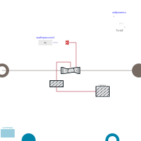
Information
1. Purpose of model
Model for heat recovery steam generator based on pinch point analysis.
The model has been developed to account for the load dependend effect of the water-steam side on the gas outlet temperature without the necessity to use dynamic balance equations for the water/steam side.
It is thus a compromise of numerical robustness and calucations speed as well as physical insight.
2. Level of detail, physical effects considered, and physical insight
- The outlet temperatures of air and steam are determined from pinch-point analysis.
- No detailled design information, such as surface areas have to be known.
- Air side outlet temperature dynamics is artificially corrected with PT1, according to thermal energy storage in internal steel mass.
3. Limits of validity
- This model is only valid for once through/benson type heat recovery steam generator with a single pressure level. For these, the pinch point is at the evaporator outlet (in gas flow direction).
- The air flow direction is assumed as vertical.
- A constant pinch point and approach point temperature difference is used.
- At very low loads, such as during start up and cool down, a minimum water flow rate is assured in the evaporator by means of a blow down flow.
4. Interfaces
- Air Inlet
- Air Outlet
- Water inlet
- Steam Outlet
5. Nomenclature
(no remarks)
6. Governing Equations
The air temperature at the pinch point is determined from the water saturation temperature at the steam outlet pressure, as set by steam turbine or bypass.
The heat available from the gas flow upstream of this point is used for steam generation and superheating and determines the steam and feedwater massflow.
7. Remarks for Usage
(no remarks)
8. Validation
The model has been validated with the heat recovery steam generator of the Electric Thermal Energy Storage demonstration plant of Siemens Gamesa Renewable Energy in Hamburg-Bergedorf, Germany.
9. References
[1] V.L. Eriksen (Ed.), Heat recovery steam generator technology, Woodhead Publishing, an imprint of Elsevier, Duxford, United Kingdom, 2017.
[2] V. Ganapathy, Waste heat boiler deskbook, Fairmont Press, Lilburn, GA, 1991.
[3] M. von der Heyde, Abschlussbericht zum Teilprojekt der TUHH im Verbundforschungsprojekt Future Energy Solution (FES), BMWI 03ET6072C, 2021
[4] M. von der Heyde, Electric Thermal Energy Storage based on Packed Beds for Renewable Energy Integration, Dissertation, Hamburg University of Technology, 2021
10. Version History
First Version in 04.2020 for the research project Future Energy Solution (FES) by Michael von der Heyde (heyde@tuhh.de)
Parameters
| Type | Name | Default | Description |
|---|---|---|---|
| Geometry | |||
| SI.Length | z_in | height | Inlet position from bottom |
| SI.Length | z_out | 0.1 | Outlet position from bottom |
| SI.Length | length | 3 | Length of Steam Generator |
| SI.Length | height | 10 | Height of Steam Generator (gas flow direction) |
| SI.Length | width | 3 | Width of Steam Generator |
| SI.Length | wall_thickness | 0.005 | wall thickness |
| Fundamental Definitions | |||
| Integer | N_cv | 3 | Number of control volumes |
| TILMedia.GasTypes.BaseGas | medium1 | simCenter.airModel | Medium to be used for gas flow |
| TILMedia.VLEFluidTypes.BaseVLEFluid | medium2 | simCenter.fluid1 | Medium for steam side |
| SI.Temperature | T_set_steam | 273.15 + 480 | Steam temperature setpoint |
| SI.Temperature | Delta_T_PP | 10 | Pinch point temperature difference |
| SI.Temperature | Delta_T_AP | 5 | Approach point temperature difference |
| SI.Temperature | Delta_T_hot_min | 30 | Hot side minimum temeprature difference |
| SI.HeatFlowRate | Q_flow_nom | 5e6 | Nominal heat flow rate |
| SI.MassFlowRate | m_flow_water_evap_min | 1 | Minimum water mass flow, as required in evaporator pipes |
| Initialisation | |||
| Boolean | useHomotopy | simCenter.useHomotopy | True, if homotopy method is used during initialisation |
| SI.Temperature[N_cv] | T_start | fill(simCenter.T_amb_start, N_cv) | Start values of gas side temperatures |
| SI.Pressure[N_cv] | p_start | fill(simCenter.p_amb_start, N_cv) | Start values of gas side pressures |
| SI.MassFraction[medium1.nc - 1] | xi_start | medium1.xi_default | Start values of gas side mass fractions |
| Integer | initOptionShell | 0 | Type of shell initialisation |
| Time Response Definition | |||
| SI.Time | timeConstant_air | 100 | Time constant according to thermal capacity of internal mass |
| Numerical Stability | |||
| SI.MassFlowRate | m_flow_air_small | 1 | Small air mass flow rate (No heat transfer below value) |
| Nominal Values | |||
| SI.MassFlowRate | m_flow_nom | 10 | Nominal mass flow |
| SI.Pressure | p_nom | simCenter.p_amb_start | Nominal pressure |
| SI.Pressure | Delta_p_nom | 1e3 | Nominal pressure loss |
| SI.Temperature | T_nom | simCenter.T_amb_start | Nominal temperature |
| Summary and Visualisation | |||
| Boolean | showData | false | True if a data port containing p,T,h,s,m_flow shall be shown, else false |
| Boolean | showExpertSummary | true | True, if expert summary should be applied |
Connectors
| Type | Name | Default | Description |
|---|---|---|---|
| ClaRa.Basics.Interfaces.GasPortIn | gasInlet | ||
| ClaRa.Basics.Interfaces.GasPortOut | gasOutlet | ||
| ClaRa.Basics.Interfaces.FluidPortIn | feedwater | ||
| ClaRa.Basics.Interfaces.FluidPortOut | livesteam |
Components
| Type | Name | Default | Description |
|---|---|---|---|
| TransiEnt.SimCenter | simCenter | ||
| ClaRa.Basics.ControlVolumes.GasVolumes.VolumeGas_L4_advanced | airVolume | ||
| TransiEnt.Components.Heat.PrescribedHeatFlowAdvanced | heatExchange | ||
| Insulation | insulation | ||
| TILMedia.Gas_pT | air_PP | Gas object at outlet port | |
| Modelica.Blocks.Sources.RealExpression | realExpression2 | ||
| Summary | summary | ||
| TILMedia.VLEFluid_ph | liveSteam | ||
| TILMedia.VLEFluid_ph | feedWater | ||
| TILMedia.VLEFluid_pT | steam_out | ||
| TILMedia.VLEFluid_pT | water_AP | ||
| TILMedia.VLEFluid_ph | water_blowDown | ||
| ClaRa.Basics.ControlVolumes.SolidVolumes.ThinPlateWall_L4 | wall | ||
| Modelica.Blocks.Continuous.FirstOrder | airDynamics | ||
| SI.Temperature | T_steam_out | Steam Outlet Temperature | |
| SI.Temperature | T_AP | Aproach Point Temperature | |
| SI.Temperature | T_PP | Pinch Point Temperature | |
| SI.Temperature | T_s | Saturation temperature | |
| SI.EnthalpyMassSpecific | h_air_out_min | Minimum air outlet enthalpy (if cooled to feedwater temperature) | |
| SI.EnthalpyMassSpecific | h_s | steam enthalpy at evaporator outlet | |
| SI.EnthalpyMassSpecific | h_f | water enthalpy at evaporator outlet | |
| Real | bd | Blow Down Rate | |
| SI.Temperature | T_steam_out_max | Max steam outlet temperature | |
| SI.HeatFlowRate | Q_flow_avail_evapAndSup | Available Heat Flow Rate in evaporator and superheater | |
| SI.HeatFlowRate | Q_flow_avail_eco | Available Heat Flow Rate in economizer | |
| SI.MassFlowRate | m_flow_max_evap | maximum water/steam mass flow according to available heat flow rate in evaporator | |
| SI.MassFlowRate | m_flow_max_eco | maximum water/steam mass flow according to available heat flow rate in economizer | |
| SI.MassFlowRate | m_flow_steam | actual water/steam mass flow | |
| SI.MassFlowRate | m_flow_nobd | water/steam mass flow without required blow down flow | |
| SI.MassFlowRate | m_flow_bd | blow down water mass flow | |
| SI.MassFlowRate | m_flow_air | air/gas mass flow | |
| SI.HeatFlowRate | Q_flow_eco | Actual transferred heat flow rate in economizer | |
| SI.HeatFlowRate | Q_flow_evap | Actual transferred heat flow rate in evaporator | |
| SI.HeatFlowRate | Q_flow_sup | Actual transferred heat flow rate in superheater | |
| SI.HeatFlowRate | Q_flow | Actual transferred overall heat flow rate | |
| SI.Power | P_check_overall | Residuum power for verification purpose | |
| SI.Power | P_check_airSide | Residuum power for verification purpose | |
| SI.Energy | E_check_airSide | Residuum energy for verification purpose | |
| SI.Energy | E_check_overall | Residuum energy for verification purpose |
Contents
| Name | Description |
|---|---|
 Outline Outline | |
 Summary Summary | |
 PressureLoss PressureLoss | |
 HeatTransferExternal HeatTransferExternal | |
 Insulation Insulation |