
modelBEVOnboardCharger
Information
1. Purpose of model
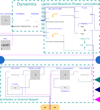
This model calculates the has the purpose of empiricially modeling an onboard charger of electric vehicles charging in non-public charging infrastructures (wallboxes). The model calculates for the setpoint of the battery active power consumption, the conversion losses and the reactive power profile based on empirical measurement profiles. An additional use case is the limitation or external setting of an active power consumption, which is implemented over an expandable connector (controlBus).
2. Level of detail, physical effects considered, and physical insight
Model is based on empiric equations for loss and reactive profile calculation and measurement data. The exact conversion behavior of the onboard charger (switching, frequency, etc.) are not included.
3. Limits of validity
The calculation of the loss and reactive power is
4. Interfaces
Input:
P_request for direct normal irradiation
SOC for diffuse horizontal irradiation
isConnected for ambient temperature
controlBus for P_limit, SignalActive and P_input (conditional parametrization based on the parameter controlType)
epp_battery for the PQ boundary of the electric vehicle battery and its active power consumption
Output:
epp_grid for connection to a complex root mean square grid simulation
5. Nomenclature
See parameter and variable descriptions in the code.
6. Governing Equations
The equations 6.3 - 6.6 are calculated first before 6.1 and 6.2 are calculated due to the sequential structure of the model.
6.1. Consumption efficiency
The consumption efficiency is calculated for the requested power. eta_over_P_grid_and_V_grid is a two-dimensional look-up table with P and epp_grid.v as input.
P_grid * eta_over_P_grid_and_V_grid.y = P_set;
P_loss = P_grid * (1-eta_over_P_grid_and_V_grid.y);
6.2. Reactive power profile
The reactive power is calculated for the requested power. Q_grid_over_P_grid_and_V_grid is a two-dimensional look-up table with P and epp_grid.v as input.
Q = Q_grid_over_P_grid_and_V_grid.y = f(P, epp_grid.v);
6.3. Power setpoint
P is calculated by:
if SOC > SOC_stop:
P = 0;
else
P = P_request;
end if;
6.4. Active Power Limitation
P is altered by:
if controlType == controlType.Limit_P and SignalActive then
P = min(P, controlBus.P_limit);
end if;
6.5. Active Power Setting
P is altered by:
if controlType == controlType.External_P and SignalActive then
P = controlBus.P_input;
P = min(P_request, controlBus.P_input);
end if;
6.6. Connection checking
P is altered by:
if isConnected then
P = P;
else
P = 0;
end if;
7. Remarks for Usage
Choose the type of empirical charger data but altering the parameter Charger_params. This changes the look-up tables in eta_over_P_grid_and_V_grid and Q_grid_over_P_grid_and_V_grid.
8. Validation
The model has been validated against the measurement data which were the bases for the empirical approach. Additionally a comparison with literature information about efficiency and reactive power was performed. The quality of the efficiency measurements was confirmed. After revalidating the data, the reactive power still differed from the data in the literature source. [1]
9. References
[1] K. Sevdari, L. Calearo, B. H. Bakken, P. B. Andersen, und M. Marinelli, “Experimental Validation of Onboard Electric Vehicle Chargers to Improve the Efficiency of Smart Charging Operation,” Sustainable Energy Technologies and Assessments, Bd. 60, S. 103512, Dec. 2023.
10. Version History
BEVOnboardCharger by Tom Steffen, Techische Universität Hamburg, Institut für Elektrische Energietechnik, 2025
Parameters
| Type | Name | Default | Description |
|---|---|---|---|
| TransiEnt.Consumer.Electrical.ElectricVehicle.Characteristics.Renault_Zoe_R110 | Charger_Params | TransiEnt.Consumer.Electrical.ElectricVehicle.Characteristics.Renault_Zoe_R110() | |
| Electric | |||
| Modelica.Units.SI.Power | P_nominal | 11000 | Nominal charge and discharge power |
| Modelica.Units.SI.Voltage | V_nominal | 400 | Nominal voltage |
| Real | SOC_stop | 1.0 | General state of charge for stop of the charging process |
| Dynamic | |||
| Real | t_deadTime | 2 | Battery reaction dead time on set value |
| Real | tau_dynamics | 3 | Battery dynamic reaction on set value |
| External Control | |||
| ControlType | controlType | TransiEnt.Basics.Types.ControlType.Internal | Type of control (see enumeration) |
Connectors
| Type | Name | Default | Description |
|---|---|---|---|
| TransiEnt.Basics.Interfaces.General.ControlBus | controlBus | ||
| TransiEnt.Basics.Interfaces.Electrical.ElectricPowerOut | P_set | ||
| TransiEnt.Basics.Interfaces.Electrical.ComplexPowerPort | epp_grid | ||
| TransiEnt.Basics.Interfaces.Electrical.ComplexPowerPort | epp_battery | ||
| Modelica.Blocks.Interfaces.RealInput | SOC | ||
| TransiEnt.Basics.Interfaces.Electrical.ElectricPowerIn | P_bat_request | ||
| Modelica.Blocks.Interfaces.BooleanInput | isConnected | Boolean Input considering wether the EV is connected to the grid when not driving |