
modelConsumer
Information
Purpose of model
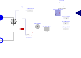
A model of a heat consumer for district heating networks. It consists of a pump, a heat exchanger, a thermal capacity, a thermal conductor and a P-controller. The P-Controller sets the mass flow rate through the pump so that the temperature of the thermal capacity (which represents the room temperature of the building) is kept constant. The heat carrier flows through the inlet, the pump and the heat exchanger, from where the heat is transported to the thermal capacity. The thermal capacity is connected with a thermal conductor via a heat port. A heat flow rate is calculated with a temperature difference between the thermal capacity and a temperature boundary that defines an ambient temperature.
This consumer model is used for the simulation of district heating networks. It calculates the mass flow rate flowing through the consumer, which is important for the numerics of a district heating network simulation. Therefore, a pressure difference has to be given by the hydraulic grid. The mass flow rate is limited by a parameter (m_flow_nom) inside the P-Controller. The calculation of the mass flow rate is independent of the pressure difference at the inlet and outlet. Therefore, the user has to pick sensible pressure values inside the hydraulic grid. An example of a pressure control is given in: TransiEnt.Examples.Heat.Largescale_DHN
Level of detail, physical effects considered, and physical insight
- P-controler
- heat losses from the building to the environemnt
- a thermal capacity of the buildings
References
The model was used and verified in the following publication:
[1] Westphal, J.; Brunnemann, J.; Speerforck, A.; Enabling the dynamic simulation of an unaggregated, meshed district heating network with several thousand substations;Energy; 2025
Version History
Model was inserted by Jan Westphal (j.westphal@tuhh.de) August 2025
Parameters
| Type | Name | Default | Description |
|---|---|---|---|
| Real | multiplicationFactor | 1 | Factor for the heat flow rate multiplication (for upscaling of consumer) |
| Real | G | 155.737 | Thermal Conuctivity of the thermal resistor |
| SI.HeatCapacity | C | 570000 | Thermal capacity of the heat capacitor |
| SI.PressureDifference | delta_p_nom | 0.1e5 | Nominal pressure difference of the valve inside the consumer |
| SI.MassFlowRate | m_flow_nom | 0.18 | Nominal mass flow rate of the water (used in the valve) |
| SI.HeatFlowRate | Q_flow_nom | 8e3 | Nominal heat flow rate (used in the heat exchanger) |
| SI.Temperature | T_room | 295.15 | Set value for room temperature |
| SI.SpecificHeatCapacity | cp | 4186 | |
| Boolean | useInput | false | |
| SI.Time | tau_i | 1000 | Constant for integrator part of PI-controller |
| Real | k | 20 | Constant for proportional part of PI-controller |
| Real | y_max | m_flow_nom | Max. opening of valve |
| Real | y_min | 0.0001 | Min. opening of valve |
Connectors
| Type | Name | Default | Description |
|---|---|---|---|
| TransiEnt.Basics.Interfaces.Thermal.FluidPortIn_simple | inlet | ||
| TransiEnt.Basics.Interfaces.Thermal.FluidPortOut_simple | outlet | ||
| Modelica.Blocks.Interfaces.RealInput | AmbientTemperatureIn |
Components
| Type | Name | Default | Description |
|---|---|---|---|
| SI.HeatFlowRate | Q_flow_C | ||
| Modelica.Thermal.HeatTransfer.Components.HeatCapacitor | heatCapacitor1 | ||
| Modelica.Thermal.HeatTransfer.Components.ThermalConductor | thermalConductor1 | ||
| TransiEnt.Components.Heat.HeatFlowMultiplier | heatFlowMultiplier | ||
| Modelica.Thermal.HeatTransfer.Sources.PrescribedTemperature | AmbientTemperature1 | ||
| TransiEnt.Components.Heat.SimplePump_mflow | pump | ||
| Modelica.Blocks.Sources.RealExpression | SetTemperature | ||
| Modelica.Thermal.HeatTransfer.Celsius.TemperatureSensor | temperatureSensor1 | ||
| TransiEnt.Components.Heat.HeatExchanger | heatExchanger1 | ||
| Modelica.Blocks.Continuous.LimPID | PID1 | ||
| Modelica.Blocks.Sources.RealExpression | SetTemperature2 | ||
| Modelica.Blocks.Sources.RealExpression | SetTemperature3 | ||
| Modelica.Blocks.Sources.RealExpression | SetTemperature4 | ||
| Modelica.Blocks.Sources.Trapezoid | trapezoid |