
modelRoomHeating
Information
Model equations
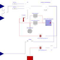
The RoomHeating model describes basic building heating thermodynamics. A PI controller with anti-windup controls the building temperature by calculating the heat flow. A limiter with variable upper limit restricts the maximal possible heat flow between the heat exchanger (floor heating) and the room itself. The heat transfer is simplified by calculating:
Q = kA * (theta_supply - theta_room)
- kA: Heat transfer coefficient between floor heating and room
- theta_supply: Supply temperature
- theta_room: Room temperature
The kA Value is calculated by the nominal heating load (NHL) at nominal temperature difference. It is assumed, that the floor heating is designed for this case:
Option 1
The kA value is calculated by NHL and a fixed assumed temperature difference at nominal operating conditions.
kA = NHL / (theta_supply_nom - theta_room)
- NHL: Nominal Heating Load
- theta_supply_nom: Nominal room temperature (usually 21 deg C)
Option 2 (default)
Calculation based on nominal k Values for different buildings. From a given U_total value, the construction year of the building is derived. Based on this number, the corresponding kA-value is calculated by a construction year specific nominal supply temperature for the heating system. The numbers are derived from the DIN EN 12831 Part 1.
Further informations
Between building and environment, the heat flow is calculated by conduction (thermal transmittance) and convection (ventilation). The coefficiencts should be calculated externally and are affected by many assumptions. The same applies to the calculation of the NHL.
In order to consider the inertia of the floor heating, a first order block introduces a delay between the controller output and the heat flow rate. Otherwise, incidetally, there is no delay in the controller loop making the PI controller obslote. Neglecting the intertia, a simple P controller with infinite gain would be sufficient, but is physically not meaningful.
Initialization
There are two possible initalization methods for this block, as defined in Modelica.Blocks.Types.Init
initType |
|
NoInit |
No initialization. States are zero |
SteadyState |
Initialization in steady state |
InitialState |
Not applicable |
InitialOutput |
Not applicable |
- NoInit: The system is initialized with states equal to zero. This is equivalent to a switched off system for simulation start. It can be useful to if the start of all components and controllers should be simulated.
- SteadyState: The system is initialized in steady state. All derivatives are zero, and the states are calculated accordingly.
Parameters
| Type | Name | Default | Description |
|---|---|---|---|
| Modelica.Units.SI.HeatCapacity | C | 30e6 | Heat capacity of consumer (= cp * m) |
| Modelica.Units.SI.ThermalConductance | G_conductance | 200 | Constant thermal conductance of consumer |
| Modelica.Units.SI.ThermalConductance | G_ventilation | 100 | Heat dissipation due to ventilation (calculated as thermal conductance) |
| Modelica.Units.SI.CoefficientOfHeatTransfer | U_total | total heat transfer coefficient of building | |
| Modelica.Units.SI.Area | A_living | 100 | Living area |
| Real[2,2] | T_supply_per_year | [1995, 45; 2015, 36] | |
| Real[2,2] | U_per_year | [1995, 0.51; 2015, 0.35] | |
| Modelica.Units.SI.HeatFlowRate | NHL_calc | NHL*1.3 | |
| Integer | construction_year | integer(floor(Modelica.Math.Vectors.interpolate(Modelica.Math.Vectors.reverse(U_per_year[:, 2]), Modelica.Math.Vectors.reverse(U_per_year[:, 1]), U_total))) | |
| Modelica.Units.SI.ThermalConductance | kA_floor | NHL/(Modelica.Math.Vectors.interpolate(T_supply_per_year[:, 1], T_supply_per_year[:, 2], construction_year) - 21) | |
| Nominal values | |||
| Modelica.Units.SI.HeatFlowRate | NHL | 10e3 | Nominal heating load |
| Modelica.Units.SI.Temperature | T_stor_nom | 273.15 + 45 | Nominal supply temperature at nominal conditions |
| Modelica.Units.SI.Temperature | T_room_nom | 273.15 + 21 | Nominal room temperature |
| Modelica.Units.SI.Temperature | T_amb_nom | 273.15 - 10 | Nominal ambient temperature |
| Initialization | |||
| Modelica.Units.SI.Temperature | T_room_start | 273.15 + 21 | Initial room temperature |
| Init | initType | Init.NoInit | Type of initialization (1: no init, 2: steady state, others do not apply) |
| Controller | |||
| Real | k_P | 10000 | Gain of PI controller |
| Real | k_Ti | 60 | Integrator time constant of PI controller |
| External Control | |||
| ControlType | controlType | TransiEnt.Basics.Types.ControlType.Internal | Type of control (see enumeration) |
Connectors
| Type | Name | Default | Description |
|---|---|---|---|
| TransiEnt.Basics.Interfaces.General.TemperatureIn | T_amb | ||
| TransiEnt.Basics.Interfaces.General.TemperatureIn | T_room_set | ||
| Modelica.Thermal.HeatTransfer.Interfaces.HeatPort_a | heatPort_supply | ||
| TransiEnt.Basics.Interfaces.General.TemperatureIn | T_room_offset | ||
| Modelica.Blocks.Interfaces.RealOutput | T_bt_min | Minimal buffer tank storage temperature needed for keeping nominal room temperature |