modelHeatPumpPartialLoad

Extends from TransiEnt.Basics.Icons.HeatPump.
Information
1. Purpose of model
Semi-empirical heat pump model whose coefficient of performance (COP) depends on both the temperature lift and the partial load. The model requires only two fitting parameters (b1, b2) and is intended for energy system simulations where a low parametrization effort and a high computational efficiency are required.
2. Level of detail, physical effects considered, and physical insight
L1: Explicit algebraic COP correlation without states, derived from the entropy and energy balance of the inner (refrigerant) cycle. Physical effects considered:
- Temperature lift via the Carnot COP of the refrigerant temperatures Thot (condensing) and Tcold (evaporating)
- Partial load via an empirical correlation for the internal entropy generation rate (exponential in the heat flow rate, linear in Thot/Tcold − 1)
- Heat transfer between refrigerant and secondary fluids via constant temperature differences (3 K for liquids, 8 K for gases)
- Steady-state energy balance of the heat sink fluid with real fluid properties (TILMedia)
Physical insight: The COP approaches the Carnot COP for a vanishing internal entropy generation rate and never exceeds it. For a positive temperature lift the COP is positive. The COP tends to zero for very small and for very large heat flow rates, so that the second-law efficiency COP/COPCarnot has its maximum at partial load.
3. Limits of validity
- Only for subcritical cycles with pure or nearly azeotropic refrigerants (e.g. R410A, R134a).
- The correlation for the internal entropy generation rate was established from measurements of a single heat pump (Abid et al. 2021b). It may deviate for other designs, e.g. two-stage cycles or cycles with economiser.
- Heat transfer is modelled with constant temperature differences only. They are fixed (3 K for liquids, 8 K for gases) and cannot be parametrized.
- Steady state: no thermal inertia, no on/off cycling, no minimum partial load, no capacity limit (the heat flow set point is always met) and no defrosting.
- No pressure loss on the heat sink side.
4. Interfaces
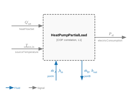
heatFlowSet: set point of the heat flow rate to the heat sink in W; negative values mean heat supplied to the heat sink (Signal, input)
sourceTemperature: inlet temperature of the heat source in K (Signal, input)
electricConsumption: electric power consumption of the heat pump in W, positive (Signal, output)
portA: heat sink fluid inlet, e.g. return of a heating network (Fluid, inlet)
portB: heat sink fluid outlet, e.g. supply of a heating network (Fluid, outlet)
5. Nomenclature
|
heatFlowSet |
set point of the heat flow rate to the heat sink (negative: heat supplied) [W] |
|
electricConsumption |
electric power consumption [W] |
|
COP |
coefficient of performance [-] |
|
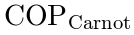
COP_c_inner |
Carnot COP of the refrigerant temperatures [-] |
|
T_hot |
condensing temperature of the refrigerant [K] |
|
T_cold |
evaporating temperature of the refrigerant [K] |
|
sinkTemperature |
heat sink outlet (supply) temperature [K] |
|
deltaT_sink |
temperature difference between refrigerant and heat sink [K] |
|
deltaT_source |
temperature difference between heat source and refrigerant [K] |
|
— |
internal entropy generation rate of the refrigerant cycle; not a model variable [W/K] |
|
— |
loss coefficient; not a model variable [W/K] |
|
b1 |
fitting parameter, pre-factor of the loss coefficient [W/K] |
|
b2 |
fitting parameter, exponent coefficient of the loss coefficient [1/W] |
|
portA.m_flow |
mass flow rate at portA [kg/s] |
|
portB.m_flow |
mass flow rate at portB [kg/s] |
|
hIn |
specific enthalpy of the inflowing heat sink fluid [J/kg] |
|
hOut |
specific enthalpy of the heat sink fluid at the outlet [J/kg] |
|
portA.p |
pressure at portA [Pa] |
|
portB.p |
pressure at portB [Pa] |




6. Governing Equations
Refrigerant temperatures from constant temperature differences to the secondary fluids (3 K for liquids, 8 K for gases):

Empirical correlation for the internal entropy generation rate, linear in the temperature ratio and exponential in the heat flow rate:

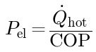
Inserting the correlation into the balances and solving for COP = Q̇hot/Pel gives the explicit COP correlation with the Carnot COP of the refrigerant temperatures:

Electric power consumption:
Steady-state energy balance of the heat sink fluid; the heat flow rate follows the set point:

Mass balance and pressure of the heat sink fluid (no pressure loss):

7. Remarks for Usage
- Sign convention: heatFlowSet < 0 means heat supplied to the heat sink. For heatFlowSet ≥ -1 W the heat pump is off; then COP = 0, electricConsumption = 0 and the heat sink fluid leaves with unchanged specific enthalpy.
- The mass flow rate of the heat sink fluid has to be imposed externally, e.g. by a pump or a mass flow boundary. A zero mass flow rate (division by zero) is caught by a minimum mass flow rate of 1e-5 kg/s.
- The supply temperature is not controlled; it results from the energy balance of the heat sink fluid.
- Requires an inner simCenter (TransiEnt.SimCenter); the heat sink medium defaults to simCenter.fluid1.
- The model terminates the simulation if Thot ≤ Tcold while the heat pump is on.
- heatSinkType and heatSourceType select the temperature difference between refrigerant and secondary fluid (Liquid: 3 K, Gas: 8 K).
- Parametrization: choose a predefined heat pump with selectHP or set useCustomizedParameter = true and define b1_custom and b2_custom. The fit requires at least two operating points with different heat flow rates, which should cover a range of heat flow rates as wide as possible. For the fit, Thot and Tcold are calculated with the same constant temperature differences as in the model.
Predefined parameter sets:
selectHP |
Heat pump |
b1 [W/K] |
b2 [1/W] |
Source |
1 |
60 kW brine to water |
21.24 |
3.74e-5 |
[source to be added] |
2 |
15 kW air to water |
4.9 |
1.6e-4 |
[source to be added] |
3 |
20 MW water to water |
5496 |
5.07e-8 |
[source to be added] |
8. Validation
The COP correlation was validated against measurement data of four heat pumps: an air-to-water heat pump with R410A (Abid et al. 2021a), a water-to-water heat pump with R134a (Skye 2022) and the brine-to-water heat pumps ecoGEO+ 45 kW and 60 kW with R410A (ECOFOREST 2025). The mean absolute percentage error (MAPE) of the COP lies between 1.8 % and 7.4 %.
Tested in check model "HeatPump_PartialLoad.TestHeatPumpPartialLoad"
9. References
Abid, M.; Hewitt, N.; Huang, M.-J.; Wilson, C.; Cotter, D., 2021a: Performance Analysis of the Developed Air Source Heat Pump System at Low-to-Medium and High Supply Temperatures for Irish Housing Stock Heat Load Applications. Sustainability 13(21), 11753, doi:10.3390/su132111753.
Abid, M.; Hewitt, N.; Huang, M. J.; Wilson, C.; Cotter, D., 2021b: Experimental Study of the Heat Pump with Variable Speed Compressor for Domestic Heat Load Applications.
Skye, H. M., 2022: Data for NIST Technical Note: Validation and Optimization with a Vapor Compression Cycle Model Accounting for Refrigerant Thermodynamic and Transport Properties. National Institute of Standards and Technology (NIST), https://data.nist.gov/od/ds/ark:/88434/mds2-2613/Experiment%20-%20All%20-%20Rev_1_5.zip.
ECOFOREST, 2025: Technical Datasheets Heat pumps (ecoGEO+ series), DS_HP_EN_v2025_01.
10. Version History
Model created by Michael Vieth (michael.vieth@tuhh.de) on 02.10.2026
Parameters
| Type | Name | Default | Description |
|---|---|---|---|
| Real | b1 | if useCustomizedParameter then b1_custom else hpCoeffs[selectHP, 1] | b1 used in model |
| Real | b2 | if useCustomizedParameter then b2_custom else hpCoeffs[selectHP, 2] | b2 used in model |
| Secondary fluids | |||
| TILMedia.VLEFluidTypes.BaseVLEFluid | mediumHeatSink | simCenter.fluid1 | Fluid of heat sink |
| String | heatSinkType | "Liquid" | Type of heat sink fluid; sets the temperature difference between refrigerant and heat sink (Liquid: 3 K, Gas: 8 K) |
| String | heatSourceType | "Liquid" | Type of heat source fluid; sets the temperature difference between heat source and refrigerant (Liquid: 3 K, Gas: 8 K) |
| Heat pump design | |||
| Boolean | useCustomizedParameter | false | true: b1 and b2 are set by user |
| Integer | selectHP | 1 | Predefined heat pump |
| Real | b1_custom | 5 | User-defined b1 |
| Real | b2_custom | 5e-5 | User-defined b2 |
Connectors
| Type | Name | Default | Description |
|---|---|---|---|
| Modelica.Blocks.Interfaces.RealInput | sourceTemperature | Inlet temperature of the heat source | |
| Modelica.Blocks.Interfaces.RealOutput | electricConsumption | Electric power consumption of the heat pump (positive) | |
| Modelica.Blocks.Interfaces.RealInput | heatFlowSet | Set point of the heat flow rate to the heat sink (negative: heat supplied) | |
| TransiEnt.Basics.Interfaces.Thermal.FluidPortIn | portA | Heat sink fluid inlet (return) | |
| TransiEnt.Basics.Interfaces.Thermal.FluidPortOut | portB | Heat sink fluid outlet (supply) |
Components
| Type | Name | Default | Description |
|---|---|---|---|
| TransiEnt.SimCenter | simCenter | Global simulation settings (provides the default heat sink medium) | |
| Real | COP | Coefficient of performance (heat flow rate to the heat sink / electric power) | |
| Real | COP_c_inner | Carnot efficiency for inner temperatures | |
| SI.TemperatureDifference | deltaT_source | Temperature difference between refrigerant and heat source | |
| SI.TemperatureDifference | deltaT_sink | Temperature difference between refrigerant and heat sink | |
| SI.Temperature | T_hot | Condensing temperature | |
| SI.Temperature | T_cold | Evaporating temperature | |
| SI.Temperature | sinkTemperature | Heat sink outlet (supply) temperature | |
| SI.HeatFlowRate | Qflow | Heat flow rate to the heat sink fluid (negative: heat supplied; 0 if off) | |
| SI.SpecificEnthalpy | hIn | Specific enthalpy of the inflowing heat sink fluid | |
| SI.SpecificEnthalpy | hOut | Specific enthalpy of the heat sink fluid at the outlet | |
| Boolean | on | true: heat pump is on (heatFlowSet < -1 W) | |
| TILMedia.VLEFluid_ph | vleFluidOut | Fluid properties of the heat sink fluid at the outlet |