
modelDarcyFlow_vertical
Extends from ClaRa.Basics.Icons.Delta_p.
Information
1. Purpose of model
Implements the vertical Darcy momentum equation including the buoyancy body force. Computes vertical mass flow rates and Darcy velocities at all N_z+1 horizontal interfaces of the aquifer grid. When buoyancy is disabled, vertical flow is set to zero.
2. Level of detail, physical effects considered, and physical insight
L4: Resolved vertical flow field for each horizontal cell interface across the full [N_r, N_z+1] grid. Buoyancy is driven by local density differences and can be switched on/off via the Boolean parameter with_buoyancy. Inertial terms are neglected.
3. Limits of validity
- Valid for low Reynolds number flow (Darcy regime).
- With buoyancy disabled, vertical flow is identically zero (no short-circuit between layers).
4. Interfaces
No connectable ports. Variables are accessed via Modelica inner/outer mechanism from the enclosing ControlVolumeL4:
delta_p_v[N_r, N_z+1] — vertical pressure differences (outer, set by ControlVolumeL4)
rho_FM_v[N_r, N_z+1] — fluid density at horizontal interfaces (outer)
f_eta_v[N_r, N_z+2] — dynamic viscosity at interfaces (outer)
5. Nomenclature
 |
m_flow_buoyancy[N_r, N_z+1] |
vertical mass flow rate at each interface [kg/s] |
 |
v_darcy[N_r, N_z+1] |
vertical Darcy velocity at each interface [m/s] |
 |
delta_p_v |
vertical pressure difference [Pa] |
 |
k |
vertical permeability [m²] |
 |
f_eta_v |
dynamic viscosity [Pa·s] |
 |
rho_FM_v |
fluid density at interface [kg/m³] |
 |
g_n |
gravitational acceleration = 9.81 m/s² |
 |
z_diff[N_z+1] |
distance between temperature nodes of adjacent control volumes [m] |
 |
A_q[N_r] |
cross-sectional area of control volume [m²] |
6. Governing Equations
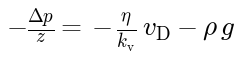
Vertical Darcy momentum equation with gravitational body force:
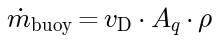
Buoyancy mass flow rate from Darcy velocity and cross-sectional area:
7. Remarks for Usage
This model must be instantiated inside ControlVolumeL4 so that the inner/outer variable declarations are satisfied. It cannot be used as a standalone component. The buoyancy switch is propagated from the Setting record.
8. Validation
Tested in check model "ATES.Validierung.Buoyancy.Val_homogenLayer"
9. References
(no remarks)
10. Version History
Model created by Markus Gillner (markus.gillner@tuhh.de), May 2026
Parameters
| Type | Name | Default | Description |
|---|---|---|---|
| Real | k | permeability of aquifer | |
| Integer | N_r | ||
| Integer | N_z | ||
| SI.Area[N_r] | A_q | cross-sectional area of control volumes | |
| SI.Length[N_r,N_z] | z_A | height of control volumes | |
| Boolean | with_buoyancy | false | logical variable for switching buoyancy physics on (true) or off (false) |
| SI.Density | rho_l | Density of undisturbed or intial fluid | |
| Real | n | porosity of aquifer |
Components
| Type | Name | Default | Description |
|---|---|---|---|
| SI.DynamicViscosity[N_r,N_z + 2] | f_eta_v | temperature and density dependent dynamic viscosity | |
| SI.PressureDifference[N_r,N_z + 1] | delta_p_v | pressure difference between two control volumes in vertical neighbourhood | |
| SI.Density[N_r,N_z + 1] | rho_FM_v | density at cross sectional area between two controlvolumes | |
| SI.MassFlowRate[N_r,N_z + 1] | m_flow_buoyancy | ||
| SI.Velocity[N_r,N_z + 1] | v_darcy | Darcy velocity V_f/A_q at each cross-sectional area |