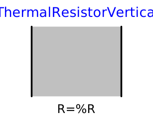
modelThermalResistorVertical

Extends from Modelica.Thermal.HeatTransfer.Interfaces.Element1D (Partial heat transfer element with two HeatPort connectors that does not store energy).
Information
1. Purpose of model
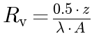
Quasi-static vertical thermal resistor for one-dimensional heat conduction between two vertically neighbouring control volumes. The thermal resistance is computed from half the control volume height and the cross-sectional area with a constant thermal conductivity. Same idea as the Modelica Standard Library ThermalConductor, but parametrized by the thermal resistance instead of the conductance, which allows a resistance of zero (no temperature difference) in series connections. This is the variant without dispersion; for hydrodynamic dispersion use ThermalResistorVertical_withDispersion.
2. Level of detail, physical effects considered, and physical insight
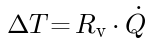
L1: Quasi-static 1D heat transport in vertical direction. No thermal storage within the resistor; the temperature drop is given by the calculated thermal resistance.
3. Limits of validity
- No thermal mass inside the resistor (instantaneous conduction).
- Constant thermal conductivity (no temperature dependency, no dispersion).
- The factor 0.5 in the resistance formula assumes the temperature node sits at the centre of the control volume.
4. Interfaces
port_a: lower heat port — heat inlet (Heat, inherited from Element1D)
port_b: upper heat port — heat outlet (Heat, inherited from Element1D)
5. Nomenclature
 |
R |
vertical thermal resistance [K/W] |
 |
lambda |
thermal conductivity of the aquifer/aquitard [W/(m·K)] |
 |
A |
cross-sectional area of control volume [m²] |
 |
z |
height of control volume [m] |
 |
Q_flow |
heat flow rate [W] (inherited from Element1D) |
 |
dT |
temperature difference across resistor [K] (inherited from Element1D) |
6. Governing Equations
Vertical thermal resistance (half-cell formulation):
Heat transport (inherited from Element1D):
7. Remarks for Usage
Used inside ImpermeableLayer to represent vertical heat conduction in the confining layers. A resistance of R = 0 is permitted and yields no temperature difference, which is convenient for series connections. Thermal properties are taken from the Subsurface_Basic (Parameters) record.
8. Validation
Tested in check model "ATES.Validierung.Buoyancy.Val_homogenLayer"
9. References
(no remarks)
10. Version History
Model created by Markus Gillner (markus.gillner@tuhh.de), May 2026
Model revised by Markus Gillner (markus.gillner@tuhh.de), June 2026
- Completed the documentation (10-section template, preferred heading style) and corrected the interface description (heat ports port_a/port_b inherited from Element1D; A is a parameter, not a Real input).
Parameters
| Type | Name | Default | Description |
|---|---|---|---|
| SI.ThermalConductivity | lambda | Heat Conductivity of the aquifer | |
| SI.Area | A | ||
| SI.Length | z | heights of all control volumes in aquifer | |
| SI.ThermalResistance | R | 0.5*z/(lambda*A) | Thermal resistance of material |
Connectors
| Type | Name | Default | Description |
|---|---|---|---|
| HeatPort_a | port_a (from Element1D) | ||
| HeatPort_b | port_b (from Element1D) |
Components
| Type | Name | Default | Description |
|---|---|---|---|
| SI.HeatFlowRate | Q_flow (from Element1D) | Heat flow rate from port_a -> port_b | |
| SI.TemperatureDifference | dT (from Element1D) | port_a.T - port_b.T |