modelWell_L4

Information
1. Purpose of model
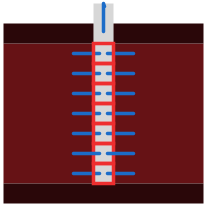
Discretized well model with N_z stacked vertical control volumes. Resolves the temperature and pressure distribution inside the well bore during injection, storage, and production phases. Distributes the total mass flow radially to the aquifer cells proportionally to each cell volume.
2. Level of detail, physical effects considered, and physical insight
L4: N_z fully discretized control volumes stacked vertically. Physical effects considered:
- Enthalpy transport in vertical direction (between adjacent well cells)
- Enthalpy exchange with aquifer cells via radial fluid ports
- Heat conduction to surrounding medium via heat ports
- Volume-proportional radial mass flow distribution during production
- Optional partial-well operation: inactive lower cells excluded during a configurable time window
3. Limits of validity
- Radial mass flow is distributed proportionally to cell volume, not driven by a pressure gradient inside the well.
- No wellbore storage effect (compressibility of fluid in well is neglected).
- Cylindrical well geometry with constant radius r_0.
4. Interfaces
![Interface diagram: fluidPortIn at top, fluidPortOut_radial[N_z] on the right, port_a[N_z] on the left](resources/TransiEnt/Resources/Images/Well_L4_interfaces.svg)
fluidPortIn: fluid inlet/outlet to the surface network — top of well (Fluid, bidirectional)
fluidPortOut_radial[N_z]: radial fluid ports to aquifer control volumes, one per vertical cell (Fluid, outlet)
port_a[N_z]: heat ports to surrounding medium per vertical cell (Heat)
5. Nomenclature
 |
T[N_z] |
cell temperature [K] |
 |
p[N_z] |
cell pressure [Pa] |
 |
h[N_z] |
specific enthalpy of cell fluid [J/kg] |
 |
H_flow_v[N_z] |
vertical enthalpy flow rate at top of each cell [W] |
 |
H_flow_r[N_z] |
radial enthalpy flow rate from aquifer into cell [W] |
 |
m_flow_v[N_z] |
vertical mass flow rate at top of each cell [kg/s] |
 |
m_flow_r[N_z] |
radial mass flow rate from/to aquifer per cell [kg/s] |
 |
port_a[j].Q_flow |
heat flow from surrounding medium into cell [W] |
 |
V_cell[N_z] |
volume of each well cell [m³] |
 |
bulk[j].d |
fluid density [kg/m³] |
 |
bulk[j].cp |
specific heat capacity of fluid [J/(kg·K)] |
 |
r_0 |
well bore radius [m] |
 |
H_cell[N_z] |
height of each well cell [m] |
6. Governing Equations
Energy balance for each well cell j (j = 2 ... N_z; cell j = 1 has no lower vertical neighbour):
![V_j*rho*cp*dT_j/dt = -H_flow_v[j-1] + H_flow_v[j] + H_flow_r[j] + Q_dot_j](resources/TransiEnt/Resources/Images/equations/equation-well-energy.png)
Mass continuity for each well cell:
![m_flow_v[j] - m_flow_v[j-1] + m_flow_r[j] = 0](resources/TransiEnt/Resources/Images/equations/equation-well-mass.png)
Volume-proportional radial mass flow distribution:
![m_flow_r[j] = -(V_j / V_well) * m_flow_v[N_z]](resources/TransiEnt/Resources/Images/equations/equation-well-distribution.png)
7. Remarks for Usage
Cell index j = 1 is the bottommost cell; j = N_z is the topmost cell connected to fluidPortIn. The parameter No_inactive_well_volumes excludes the lowest cells from the radial distribution during a defined time window [t_well_start, t_well_end], allowing partial-screen operation.
8. Validation
Tested via "ATES.Validierung.Buoyancy.Val_homogenLayer"
9. References
(no remarks)
10. Version History
Model created by Markus Gillner (markus.gillner@tuhh.de), May 2026
Parameters
| Type | Name | Default | Description |
|---|---|---|---|
| Integer | N_z | 4 | Number of vertical volume elements |
| SI.Pressure | p_initial | 100000 | Initial pressure of all discretised volumes of the well |
| SI.Temperature | T_initial | 298.15 | Initial temperature of all discretised volumes of the well |
| SI.Radius | r_0 | 0.1 | Radius of the well |
| SI.Length[N_z] | H_cell | fill(5, N_z) | Heigth of each discretised element of the well: counting is from bottom to top |
| SI.Volume[N_z] | V_cell | {(pi*r_0^2*H_cell[i]) for i in 1:N_z} | Volume of each discretised element of the well: counting is from bottom to top |
| Integer | No_inactive_well_volumes | 0 | Number of well volumes that takes a mass flow out of the aquifer --> only in production phase |
| SI.Volume | V_well_prod | sum(V_cell[j] for j in 1 + No_inactive_well_volumes:N_z) | Volume of the well taking inactive volumes of well into account |
| SI.Volume | V_well | sum(V_cell) | Volume of the well |
| SI.Time | t_well_start | 25056000 | start time when in production or injection phase only a part of the well is used |
| SI.Time | t_well_end | 28425600 | end time of well beeing shortened |
| TILMedia.VLEFluidTypes.BaseVLEFluid | water | simCenter.fluid1 | Heat carrier |
Connectors
| Type | Name | Default | Description |
|---|---|---|---|
| TransiEnt.Basics.Interfaces.Thermal.FluidPortIn | fluidPortIn | ||
| TransiEnt.Basics.Interfaces.Thermal.FluidPortOut[N_z] | fluidPortOut_radial | ||
| Modelica.Thermal.HeatTransfer.Interfaces.HeatPort_a[N_z] | port_a |
Components
| Type | Name | Default | Description |
|---|---|---|---|
| SI.Pressure[N_z] | p | pressure of discretised volumes | |
| SI.Temperature[N_z] | T | Temperature of discretised volumes | |
| SI.MassFlowRate[N_z] | m_flow_v | Mass flow in vertical direction | |
| SI.MassFlowRate[N_z] | m_flow_r | Mass flow in radial direction | |
| SI.SpecificEnthalpy[N_z] | h | Specific enthalpy of every volume | |
| SI.EnthalpyFlowRate[N_z] | H_flow_v | Enthalpy Flow Rate in vertical direction at top of volume element | |
| SI.EnthalpyFlowRate[N_z] | H_flow_r | Enthalpy Flow Rate in radial direction | |
| TILMedia.VLEFluid_pT[N_z] | bulk | ||
| TILMedia.VLEFluid_ph | vleFluidIn | ||
| TILMedia.VLEFluid_ph[N_z] | vleFluid_radial | ||
| ClaRa.SimCenter | simCenter |