modelPackedBedStorage_L4
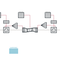
Extends from TransiEnt.Basics.Icons.PackedBedThermalStorage (Icon for packed-bed thermal storage model).
Information
1. Purpose of model
The model describes a sensible high-temperature packed-bed thermal energy storage unit. It is composed of the packed-bed, fluid in and outlet spaces, and thermal insulation. Gaseous heat transfer fluid and solid media storage material are generally assumed. It has been validated with air as heat transfer fluid and natural rock as storage material. Main focus is the
- transient behavior of the temperature field in the packed bed,
- fluid pressure loss and
- transmission heat losses to the environment.
2. Level of detail, physical effects considered, and physical insight
- The packed bed is discretized in one dimension, which is the main fluid flow direction.
- A single energy equation is used for each finite volume, meaning particle and fluid temperature are not distinct, but a mean packed-bed temperature is used. This generally holds for ideal heat transfer between the storage material and heat transfer fluid. Neverthess, the effect of a limited heat transfer between both can be still taken into account by adoption of the effective packed-bed thermal conductivity correlation for example using the approach of Vortmeyer (1974).
- An additional body force according to the Darcy-Forchheimer equation is added to the dynamic momentum balance to account for the packed bed flow resistance.
- Enclosed fluid volumes on the hot and cold side of the storage unit are included using a single control volume. They can be used to model additional pressure and heat loss at the fluid in- and outflow.
- An additional heat port is added between the packed bed and air in and outlet space. It can be used to account for other means of heat transport such as conduction, radiation or natural convection besides the advective energy transport into and out of the packed bed.
- The thermal insulation model is replaceable and can therefore consider static or dynamic heat transfer with various heat paths and insulation layers.
- A storage material medium model is required, which has an additional state variable for the specific internal energy in order to account for a temperature variant specific heat capacity.
3. Limits of validity
- The one-dimensional spatial representation leads to the plug-flow assumption, meaning no lateral temperature and velocity variations are taken into account
- No gravitational force is taken into account in the dynamic momentum balance, as a horizontal air flow direction has been used at all tested plants so far.
- Natural convection inside the packed bed is not taken into account
- The convective heat transfer between packed bed and insulation depends on the lateral packed bed temperature profile. This profile generally requires a dynamic model for the heat transfer coefficient. Nevertheless, several correlations are implemented, but the user should be aware of this.
- The thermal capacity and flow resistance of the grating used to hold the storage material at in and outlet is not taken into account, but added to the packed bed volume
4. Interfaces
- Hot Air Inlet/Outlet
- Cold Air Inlet/Outlet
5. Nomenclature
(no remarks)
6. Governing Equations
(no remarks)
7. Remarks for Usage
- The heat transfer fluid momentum balance is dynamic to allow very small mass flows without numerical errors
- The mean sphericity describes the ratio of the surface of a set of monodisperse spheres with the same number and overall volume as the particle set to the particles set surface. It thus is not solely depended on the particles shape, but also on the particle size distribution.
8. Validation
The model has been validated with two experimental setups of Siemens Gamesa Renewable Energy in Hamburg-Altenwerder (6 MWh_th) and -Bergedorf (130 MWh_th), Germany.
9. References
[1] M. von der Heyde, Abschlussbericht zum Teilprojekt der TUHH im Verbundforschungsprojekt Future Energy Solution (FES), BMWI 03ET6072C, 2021
[2] M. von der Heyde, Electric Thermal Energy Storage based on Packed Beds for Renewable Energy Integration, Dissertation, Hamburg University of Technology, 2021
10. Version History
First Version in 04.2020 for the research project Future Energy Solution (FES) by Michael von der Heyde (heyde@tuhh.de)
Parameters
| Type | Name | Default | Description |
|---|---|---|---|
| SI.Temperature | T_start_bed_int | if linearInit then linspace(T_start_hot, T_start_cold, N_cv) else T_start_bed | |
| SI.HeatCapacityMassSpecific | cp_nom | (TILMedia.GasFunctions.specificIsobaricHeatCapacity_pTxi(medium_air, simCenter.p_amb_start, T_c, medium_air.xi_default) + TILMedia.GasFunctions.specificIsobaricHeatCapacity_pTxi(medium_air, simCenter.p_amb_start, T_d, medium_air.xi_default))/2 | |
| SI.EnthalpyMassSpecific | h_nom | TILMedia.GasFunctions.specificEnthalpy_pTxi(medium_air, p_nom, T_nom, medium_air.xi_default) | Nominal enthalpy |
| Nominal Values | |||
| SI.Power | E_flow_nom | m_flow_nom*cp_nom*(T_c - T_d) | |
| SI.Pressure | p_nom | simCenter.p_amb_start | Nominal pressure (for nominal pressure loss calculation) |
| SI.Temperature | T_nom | simCenter.T_amb_start | Nominal Temperature (for nominal pressure loss calculation) |
| SI.MassFlowRate | m_flow_nom | 10 | Nominal mass flow rate |
| SI.Pressure | Delta_p_nom_bed | 2e3 | Nominal pressure loss (used for regularization around zero) |
| SI.Temperature | T_ref | 273.15 | Reference Temperature (for nominal storage capacity calculation) |
| SI.Temperature | T_c | 273.15 + 600 | Nominal Charge Temperature (for nominal storage capacity calculation) |
| SI.Temperature | T_d | 273.15 + 20 | Nominal Discharge Temperature (for calculation of nominal rate of charge and discharge) |
| SI.Temperature | T_stop_c | 273.15 + 100 | Outlet Temperature to stop charge operation (for usable capacity ratio calculation) |
| SI.Temperature | T_stop_d | 273.15 + 520 | Outlet Temperature to stop discharge operation (for usable capacity ratio calculation) |
| Initialisation | |||
| Boolean | linearInit | true | True for linear bed temperature initialisation |
| SI.Temperature | T_start_bed | fill(293.15, N_cv) | Packed Bed Initial Temperature |
| SI.Temperature | T_start_hot | simCenter.T_amb_start | Hot Side Initial Temperature |
| SI.Temperature | T_start_cold | simCenter.T_amb_start | Cold Side Initial Temperature |
| SI.Pressure | p_start_hot | simCenter.p_amb_start | Initial hot side pressure |
| SI.Pressure | p_start_cold | simCenter.p_amb_start | Initial cold side pressure |
| SI.MassFlowRate | m_flow_start | 0 | Initial mass flow rate |
| Geometry | |||
| Real | d_v_m | 0.03 | Mean volume-equivalent diameter of storage material particles |
| Real | porosity | 0.4 | Packed-bed porosity |
| Real | sphericity | 0.8 | Packed-bed mean sphericity (see definition in documentation section) |
| SI.Length | pipe_thickness | 0.005 | Wall thickness at enclosed air spaces |
| Integer | N_cv | 10 | Number of finite control volumes in flow direction |
| Fundamental Definitions | |||
| TILMedia.GasTypes.BaseGas | medium_air | simCenter.airModel | Medium of heat transfer fluid |
Connectors
| Type | Name | Default | Description |
|---|---|---|---|
| ClaRa.Basics.Interfaces.GasPortIn | HotAirPort | ||
| ClaRa.Basics.Interfaces.GasPortOut | ColdAirPort |
Components
| Type | Name | Default | Description |
|---|---|---|---|
| TransiEnt.SimCenter | simCenter | ||
| Summary | summary | ||
| TransiEnt.Storage.Heat.PackedBedStorage_L4.Basics.PackedBedControlVolume_L4 | packedBed | ||
| Insulation_bed | insulation_bed | ||
| Insulation_hot | insulation_hot | ||
| Insulation_cold | insulation_cold | ||
| ClaRa.Basics.ControlVolumes.GasVolumes.VolumeGas_L2_advanced | air_hot | ||
| ClaRa.Basics.ControlVolumes.GasVolumes.VolumeGas_L2_advanced | air_cold | ||
| ClaRa.Components.Adapters.Scalar2VectorHeatPort | scalar2VectorHeatPort | ||
| ClaRa.Components.Adapters.Scalar2VectorHeatPort | scalar2VectorHeatPort1 | ||
| ClaRa.Basics.ControlVolumes.SolidVolumes.ThinPlateWall_L4 | thinPlateWall_L4_1 | ||
| ClaRa.Basics.ControlVolumes.SolidVolumes.ThinPlateWall_L4 | thinPlateWall_L4_2 |