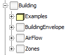
The Building package is intended to describe the
building envelope and air change, and provides components in a pure
thermal or thermo-fluid approach. It also contains generic models
of zones which can represent an entire building or a single
room.
One of the key elements of this package is the thermal wall model. It represents a 1D discrete multi-layer wall with several connectors for boundary conditions. A diagram view of this model can be seen on Figure 1. By convention, the right hand side corresponds to the inside whereas the left hand side can be both, inside or outside boundary conditions.
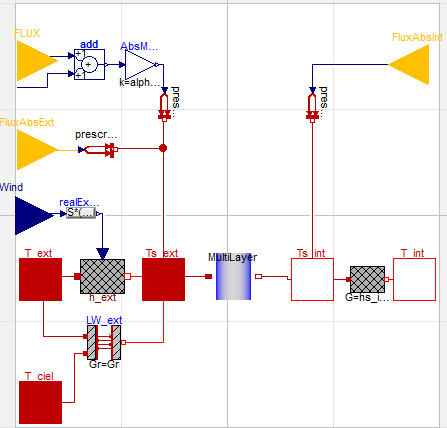
Figure 1: Diagram of the wall model
The blue component in the middle is a
HomogeneousNLayersWall model describing the conductive
part of the wall. It is based on thermal conductors and capacitors
connected in order to represent layers of homogenous material. The
causal connectors represented by yellow triangles are used to
convey short wave radiations such as solar irradiance or
transmitted solar radiation coming from the windows or the
environment. They include either the cosine of the incidence angle,
diffuse and direct flux or global flux.
The heat ports connect the model to the surround-ing temperatures.
Thanks to optional models and connections, convective heat
transfers are considered with an h coefficient either fixed or
controlled by wind speed. In the same way, the long wave radiative
heat transfer is represented either with a fixed coefficient or
with the Stefan–Boltzmann law using dry bulb and sky temperatures.
The parameters of the wall model can be easily set thanks to
various records. For instance, the parameters of the conductive
part use a replaceable WallType record which contains
the information described in Figure 2:
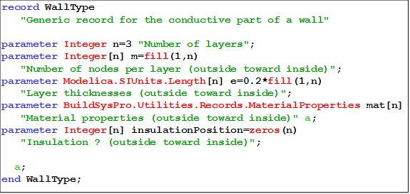
Figure 2: WallType record
A typical one-zone thermal model would be essentially composed of walls, one air node and air renewal. Figure 3 presents this simple thermal zone using combined convective and radiative heat transfers (in this example, without taking into account the wind speed nor the sky temperature). Thus, depending on the assumptions considered, other types of thermal zones can be designed. For instance, instead of distributing the transmitted solar radiation onto the floor, other weighting methods can be used depending on the solar absorption coefficients and surface areas or view factors, as in the BESTEST calculations.
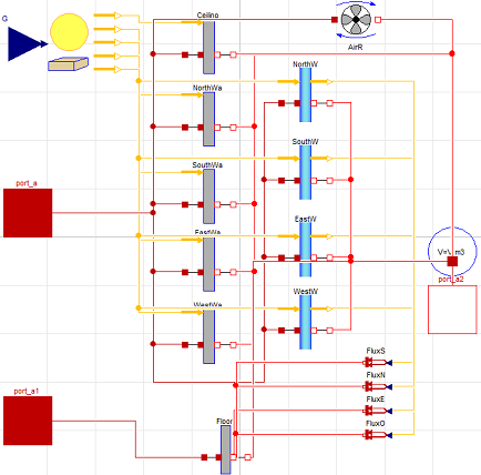
Figure 3: Diagram of a simple thermal zone
-----------------------------------------------------------------------
Licensed by EDF under a 3-clause BSD-license
Copyright © EDF 2009 - 2023
This Modelica package is free software and the use is
completely at your own risk; it can be redistributed and/or
modified under the terms of 3-clause BSD-license.
For license conditions (including the disclaimer of warranty) see
BuildSysPro.UsersGuide.License.
-----------------------------------------------------------------------
| Name | Description |
|---|---|
| Exemples de connexion de composants et/ou validation de ceux-ci | |
| Building Envelope | |
| Air Flow | |
| Zones |