
modelMSLAIT
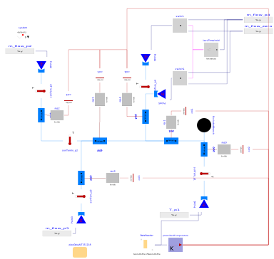
Extends from Modelica.Icons.Example (Icon for runnable examples).
Information
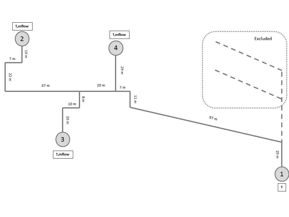
The example contains experimental data from a real district heating network. This data is used to validate this library's IBPSA.Fluid.FixedResistances.PlugFlowPipe in IBPSA.Fluid.FixedResistances.Validation.PlugFlowPipes.PlugFlowAIT. This model compares its performance with the original Modelica Standard Library pipes, using one discretization element per unit length of pipe. For a coarser discretization, please refer to MSLAIT2Nodes.
Note that these three models are identical, except for the pipe model that is used:
-
The model
IBPSA.Fluid.FixedResistances.Validation.PlugFlowPipes.MSLAIT
uses the pipe model from the Modelica Standard Library, with a fine discretization.
See the parameter
nNodes. -
The model
IBPSA.Fluid.FixedResistances.Validation.PlugFlowPipes.MSLAIT2Nodes
uses the same model as above, but sets
nNodes=2. - The model IBPSA.Fluid.FixedResistances.Validation.PlugFlowPipes.PlugFlowAIT uses the plug flow model IBPSA.Fluid.FixedResistances.PlugFlowPipe.
This comparison between different discretization levels and pipe models is made to check the influence of the discretization and pipe model on computation time and simulation accuracy.
The pipes' temperatures are not initialized, thus results of outflow temperature before approximately the first 10000 seconds should not be considered.
Test bench schematic
Calibration
To calculate the length specific thermal resistance R of the
pipe, the thermal resistance of the surrounding ground is added.
R=1/(0.208)+1/(2 lambda_g Modelica.Constants.pi) log(1/0.18)
Where the thermal conductivity of the ground lambda_g = 2.4 W/(m K).
Parameters
| Type | Name | Default | Description |
|---|---|---|---|
| Boolean | allowFlowReversal | false | = true to allow flow reversal, false restricts to design direction (port_a -> port_b) |
| Modelica.Units.SI.ThermalResistance | R | 1/(2*kIns*Modelica.Constants.pi)*log(0.18/0.0899) + 1/(2*2.4*Modelica.Constants.pi)*log(2/0.18) | Thermal resistance of main pipes |
| Modelica.Units.SI.ThermalResistance | R80 | 1/(2*0.024*Modelica.Constants.pi)*log(0.07/0.0337) + 1/(2*2.4*Modelica.Constants.pi)*log(2/0.07) | Thermal resistance of service pipes |
| Modelica.Units.SI.ThermalConductivity | kIns | 0.024 | Heat conductivity of pipe insulation material |
| Modelica.Units.SI.Length | dIns | 0.045 | Thickness of pipe insulation |
| Modelica.Units.SI.Diameter | diameter | 0.089 | Outer diameter of pipe |
| Modelica.Units.SI.MassFlowRate | m_flow_nominal | 1 | Nominal mass flow rate, used for regularization near zero flow |
| Modelica.Units.SI.Time | tauHeaTra | 6500 | Time constant for heat transfer, default 20 minutes |
Components
Contents
| Name | Description |
|---|---|
 Medium Medium |
Revisions
-
March 7, 2020, by Michael Wetter:
Replaced measured data from specification in Modelica file to external table, as this reduces the computing time.
This is for #1289. -
May 15, 2019, by Jianjun Hu:
Replaced fluid source. This is for #1072. - November 28, 2016 by Bram van der Heijde:
RemovepipVol. - August 24, 2016 by Bram van der Heijde:
Implement validation with MSL pipes for comparison, based on AIT validation. -
July 4, 2016 by Bram van der Heijde:
Added parameters to test the influence of allowFlowReversal and the presence of explicit volumes in the pipe. - January 26, 2016 by Carles Ribas:
First implementation.