This model consist of an HVAC system, a building envelope model and a model for air flow through building leakage and through open doors.
The HVAC system is a variable air volume (VAV) flow system with economizer and a heating and cooling coil in the air handler unit. There is also a reheat coil and an air damper in each of the five zone inlet branches. The figure below shows the schematic diagram of the HVAC system
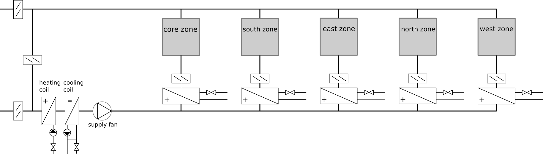
See the model Buildings.Examples.VAVReheat.BaseClasses.PartialHVAC for a description of the HVAC system, and see the model Buildings.Examples.VAVReheat.BaseClasses.Floor for a description of the building envelope.
The control is an implementation of the control sequence VAV 2A2-21232 of the Sequences of Operation for Common HVAC Systems (ASHRAE, 2006). In this control sequence, the supply fan speed is modulated based on the duct static pressure. The return fan controller tracks the supply fan air flow rate. The duct static pressure set point is adjusted so that at least one VAV damper is 90% open. The heating coil valve, outside air damper, and cooling coil valve are modulated in sequence to maintain the supply air temperature set point. The economizer control provides the following functions: freeze protection, minimum outside air requirement, and supply air cooling, see Buildings.Examples.VAVReheat.BaseClasses.Controls.Economizer. The controller of the terminal units tracks the room air temperature set point based on a "dual maximum with constant volume heating" logic, see Buildings.Examples.VAVReheat.BaseClasses.Controls.RoomVAV.
There is also a finite state machine that transitions the mode of operation of the HVAC system between the modes occupied, unoccupied off, unoccupied night set back, unoccupied warm-up and unoccupied pre-cool. In the VAV model, all air flows are computed based on the duct static pressure distribution and the performance curves of the fans. Local loop control is implemented using proportional and proportional-integral controllers, while the supervisory control is implemented using a finite state machine.
A similar model but with a different control sequence can be found in Buildings.Examples.VAVReheat.Guideline36.
ASHRAE. Sequences of Operation for Common HVAC Systems. ASHRAE, Atlanta, GA, 2006.
lat as this is now
obtained from the weather data reader.from_dp=false for exhaust air damper.Buildings.Examples.VAVReheat.BaseClasses.PartialHVAC
rather than through the model of a mixing box. Since the version of
the Guideline 36 model has no exhaust air damper, this leads to
simpler equations.