This package contains models for direct evaporation (DX) cooling coils.
The following six DX coil models are available:
| DX coil condenser | DX coil model | Properties | Control signal |
|---|---|---|---|
| Air source | Buildings.Fluid.DXSystems.Cooling.AirSource.MultiStage | Coil with multiple operating stages, each stage having a constant speed. Each stage has its own performance curve, which may represent the coil performance at different compressor speed, or the coil performance as it switches between cooling only, cooling with hot gas reheat, or heating only. | Integer; 0 for off, 1 for first stage, 2 for second stage, etc. |
| Air source | Buildings.Fluid.DXSystems.Cooling.AirSource.SingleSpeed | Single stage coil with constant compressor speed | Boolean signal; true if coil is on. |
| Air source | Buildings.Fluid.DXSystems.Cooling.AirSource.VariableSpeed | Coil with variable speed compressor with lower speed limit. If
the control signal is below the lower limit, the coil switches off.
It switches on if the control signal is above the lower limit plus
a hysteresis. By default, the minimum speed ratio is
minSpeRat and obtained from the coil data record
datCoi.minSpeRat. The hysteresis is by default
speDeaBanRat=0.05. |
Real number; 0 for coil off, 1 for coil at full speed. |
| Water source | Buildings.Fluid.DXSystems.Cooling.WaterSource.MultiStage | Coil with multiple operating stages, each stage having a constant speed. Each stage has its own performance curve, which may represent the coil performance at different compressor speed, or the coil performance as it switches between cooling only, cooling with hot gas reheat, or heating only. | Integer; 0 for off, 1 for first stage, 2 for second stage, etc. |
| Water source | Buildings.Fluid.DXSystems.Cooling.WaterSource.SingleSpeed | Single stage coil with constant compressor speed | Boolean signal; true if coil is on. |
| Water source | Buildings.Fluid.DXSystems.Cooling.WaterSource.VariableSpeed | Coil with variable speed compressor with lower speed limit. If
the control signal is below the lower limit, the coil switches off.
It switches on if the control signal is above the lower limit plus
a hysteresis. By default, the minimum speed ratio is
minSpeRat and obtained from the coil data record
datCoi.minSpeRat. The hysteresis is by default
speDeaBanRat=0.05. |
Real number; 0 for coil off, 1 for coil at full speed. |
The DX cooling coil models take as a control input the stage of operation, an on/off signal, or the speed of the compressor. Because the thermal response of the coil is very fast, it is important to use as the controlled variable the room air temperature, as the room air temperature has a much slower response compare to the supply air temperature. If the supply air temperature is used, then the control algorithm should be such that short-cycling is avoided.
For air source DX cooling coils, the steady-state total rate of cooling and the Energy Input Ratio (EIR) are computed using polynomials in the air mass flow fraction (relative to the nominal mass flow rate), the evaporator air inlet temperature and the outdoor air temperature. These polynomials are explained at Buildings.Fluid.DXSystems.BaseClasses.CapacityAirSource.
For water source DX coils, the steady-state total rate of cooling and the EIR are computed using polynomials in the air mass flow fraction (relative to the nominal mass flow rate), the water mass flow fraction (relative to the nominal water mass flow rate), the evaporator air inlet temperature and the condenser water inlet temperature. These polynomials are explained at Buildings.Fluid.DXSystems.Cooling.BaseClasses.CapacityWaterCooled.
If a coil dehumidifies air, a water film builds up on the evaporator. When the compressor is off, this water film evaporates into the air stream. For coils that short-cycle, this significantly decreases the dehumidification capacity of the coil. The accumulation and reevaporation of water on the evaporator coil is explained at Buildings.Fluid.DXSystems.Cooling.BaseClasses.Evaporation.
Two dynamic effects are modeled: The accumulation and
reevaporation of water at the evaporator, and the thermal response
of the evaporator. The dynamics of the evaporation is described at
Buildings.Fluid.DXSystems.Cooling.BaseClasses.Evaporation. The
dynamics of the evaporator is approximated by a first order
response where the time constant is a model parameter. Hence, the
dynamic response is similar to other models of the
Buildings.Fluid package and described at Buildings.Fluid.UsersGuide.
The coils model two separate performances, one assuming a dry
coil, and one assuming a wet coil. The dry coil is modeled using
Buildings.Fluid.DXSystems.BaseClasses.DryCoil
and the wet coil is modeled using Buildings.Fluid.DXSystems.Cooling.BaseClasses.WetCoil.
Both use the same model
Buildings.Fluid.DXSystems.BaseClasses.CapacityAirSource to
compute the cooling capacity, but the wet coil uses the wet-bulb
temperature of the air inlet instead of the dry bulb temperature to
compute the coil performance. The wet coil model computes the
humidity of the leaving air Xw,o, using the
bypass factor model.
In the cooling coil model, this humidity is compared to the
humidity at the evaporator inlet Xi. If
Xw,o-Xi > 0 the coil is assumed to
be dry, otherwise it is wet. This test is implemented in
Buildings.Fluid.DXSystems.Cooling.BaseClasses.DryWetSelector in
such a way that the transition between wet and dry coil is
differentiable.
In the heating coil model, the coil is assumed to be acting as a
dry coil at all times.
The split between sensible and latent heat ratio is computed using the apparatus dew point. This calculation is implemented in Buildings.Fluid.DXSystems.Cooling.BaseClasses.ApparatusDewPoint. Once the apparatus dew point is known, the sensible to latent heat ratio can be determined as shown in the figure below.
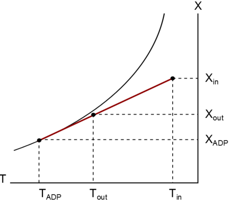
The method used is the bypass factor method, which assumes that of the leaving air, a fraction is at the same condition as the entering air, and the other fraction is at the apparatus dew point. This computation requires the ratio UA ⁄ cp, which is computed in Buildings.Fluid.DXSystems.Cooling.BaseClasses.UACp.
Once the ratio UA ⁄ cp is known, the bypass factor is a function of the current mass flow rate only. (Under the assumption that the velocity dependence of UA can be neglected.)
This model has the following limitations:
port_a to
port_b. If there is reverse flow, then no cooling is
provided and no power is consumed.