This package contains borefield models. These models can simulate any arbitrary configuration of vertical boreholes with equal lengths with both short and long-term accuracy with an aggregation method to speed up the calculations of the ground heat transfer. Examples of how to use the borefield models and validation cases can be found in Buildings.Fluid.Geothermal.Borefields.Examples and Buildings.Fluid.Geothermal.Borefields.Validation, respectively.
The following major features and configurations are supported:
dp_nominal
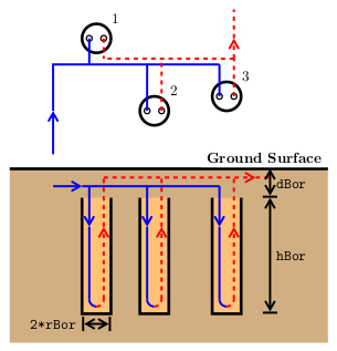
parameter is set to a non-zero value.The model is limited to the simulation of borefields with
boreholes connected in parallel, as shown on the figure below for a
single U-tube configuration. All boreholes have the same length
hBor, the same radius rBor, and are
buried at the same depth dBor below the ground surface
(also known as the inactive borehole length).
Most of the parameter values of the model are contained in the
record called borFieDat. This record is composed of
three subrecords: filDat (containing the thermal
characteristics of the borehole filling material),
soiDat (containing the thermal characteristics of the
surrounding soil), and conDat (containing all others
parameters, namely parameters defining the configuration of the
borefield). The structure and default values of the record are in
the package: Buildings.Fluid.Geothermal.Borefields.Data.
The borFieDat record can be found in the Buildings.Fluid.Geothermal.Borefields.Data.Borefield
subpackage therein. Examples of the subrecords conDat,
filDat and soiDat can be found in
Buildings.Fluid.Geothermal.Borefields.Data.Configuration,
Buildings.Fluid.Geothermal.Borefields.Data.Filling
and Buildings.Fluid.Geothermal.Borefields.Data.Soil,
respectively.
It is important to make sure that the borCon
parameter within the conDat subrecord is compatible
with the chosen borefield model. For example, if a double U-tube
borefield model is chosen, the borCon parameter could
be set to both a parallel double U-tube configuration and a double
U-tube configuration in series, but could not be set to a single
U-tube configuration. An incompatible borehole configuration will
stop the simulation.
Other than the parameters contained in the
borFieDat record, the borefield models have other
parameters which can be modified by the user. The
tLoaAgg parameter is the time resolution of the load
aggregation for the calculation of the ground heat transfer. It
represents the frequency at which the load aggregation procedure is
performed in the simulation. Therefore, smaller values of
tLoaAgg will improve the accuracy of the model, at the
cost of increased simulation times due to a higher number of events
occuring in the simulation. While a default value is provided for
this parameter, it is advisable to ensure that it is lower than a
fraction (e.g. half) of the time required for the fluid to
completely circulate through the borefield, as increasing the value
of tLoaAgg beyond this will result in non-physical
borehole wall temperatures.
The nCel parameter also affects the accuracy and
simulation time of the ground heat transfer calculations. As this
parameter sets the number of consecutive equal-size aggregation
cells before increasing the size of cells, increasing its value
will result in less load aggregation, which will increase accuracy
at the cost of computation time. On the other hand, decreasing the
value of nCel (down to a minimum of 1) will decrease
accuracy but improve computation time. The default value is chosen
as a compromise between the two.
Further information on the tLoaAgg and
nCel parameters can be found in the documentation of
Buildings.Fluid.Geothermal.Borefields.BaseClasses.HeatTransfer.GroundTemperatureResponse.
Other parameters which can be modified include the dynamics,
initial conditions, and further information regarding the fluid
flow, for example whether the flow is reversible. It is worth
noting that regardless of the energyDynamics chosen,
the steadyState parameter can be set to
true in the data record for the filling material to
remove the effect of the thermal capacitance of the filling
material in the borehole(s). The nSeg parameter
specifies the number of segments for the vertical discretization of
the borehole(s). Further information on this discretization can be
found in the "Model description" section below.
When running simulations using the borefield models, the
tmp/temperatureResponseMatrix directory within the
current directory will be checked to see if any of the borefield
configurations used in the simulation have already had their ground
temperature response calculated previously If the data doesn't
exist in the tmp/temperatureResponseMatrix folder, it
will be calculated during the initialization of the model and will
be saved there for future use.
The borefield models rely on the following key assumptions:
The borefield models are constructed in two main parts: the
borehole(s) and the ground heat transfer. The former is modeled as
a vertical discretization of borehole segments, where a uniform
temperature increase or decrease (due to heat injection or
extraction) is superimposed to the far-field ground temperature to
obtain the borehole wall temperature. The thermal effects of the
circulating fluid (including the convection resistance), of the
pipes and of the filling material are all taken into consideration,
which allows modeling short-term thermal effects in the borehole.
The borehole segments do not take into account axial effects, thus
only radial (horizontal) effects are considered within the
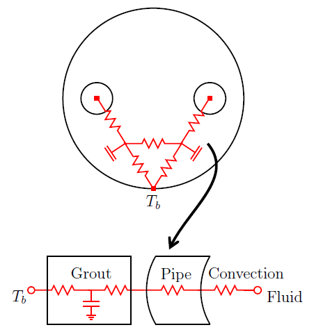
borehole(s). The thermal behavior between the pipes and borehole
wall are modeled as a resistance-capacitance network, with the
grout capacitance being split in the number of pipes present in a
borehole section. The capacitance is only present if the parameter
steadyState of the filling material data record is
false, which is the default setting. The figure below
shows an example for a borehole section within a single U-tube
configuration.
The second main part of the borefield models is the ground heat transfer, which shares a thermal boundary condition at the uniform borehole wall with all of the borehole segments. The heat transfer in the ground is modeled analytically as a convolution integral between the heat flux at the borehole wall and the borefield's thermal response factor.
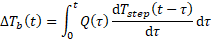
The model uses a load aggregation technique to reduce the time required to calculate the borehole wall temperature changes resulting from heat injection or extraction.
The ground heat transfer takes into account both the borehole
axial effects and the borehole radial effects which are a result of
its cylindrical geometry. The borefield's thermal response to a
constant load, also known as its g-function, is used to
calculate the thermal response in the simulation. This g-function
is stored in the tmp/temperatureResponseMatrix
subdirectory, as discussed previously in the "How to use the
borefield models" section. Further information on the ground heat
transfer model and the thermal temperature response calculations
can be found in
Buildings.Fluid.Geothermal.Borefields.BaseClasses.HeatTransfer.GroundTemperatureResponse
and
Buildings.Fluid.Geothermal.Borefields.BaseClasses.HeatTransfer.ThermalResponseFactors.gFunction.
D. Picard, L. Helsen. Advanced Hybrid Model for Borefield Heat Exchanger Performance Evaluation; an Implementation in Modelica Proc. of the 10th Intertional ModelicaConference, p. 857-866. Lund, Sweden. March 2014. https://lirias.kuleuven.be/retrieve/270880.