This model represents a heating system where the configuration Buildings.Fluid.HydronicConfigurations.ActiveNetworks.Diversion is used to modulate the heat flow rate transmitted to a constant load. Two identical secondary circuits are connected to a primary circuit with a constant speed pump. The main assumptions are enumerated below.
time=0 are defined
without considering any load diversity.is_bal is set to
true. Otherwise no fixed flow resistance is considered
in the bypass branch, only the variable flow resistance
corresponding to the bypass port of the three-way valve.When simulated with the default parameter values, this example shows the following points.
time=100) creates a concomitant flow shortage in the
second circuit with the valve fully open. However, the flow
shortage (4%) is of a much lower amplitude than the overflow
(30%). Indeed the equivalent flow resistance seen by the
pump is lower than at design conditions, leading a shift of the
operating point of the pump towards a flow rate value higher than
design, which partly compensates for the overflow.Those observations are confirmed by a sensitivity study to the following parameters.
is_bal switched from
false to trueThreeWayValve switched from
equal percentage-linear (EL) to linear-linear (LL).The overflow in the bypass branch when the valve is fully closed increases with ψ and decreases with β. It is close to 70% for ψ = 40% and β = 10%. However, the concomitant flow shortage in the other terminal unit with a valve fully open (see Figure 2) is limited to 12%. For a valve authority of β = 50% one may note that the flow shortage is below 5%, indicating that selecting the control valve with a suitable authority largely dampens the impact of an unbalanced bypass.
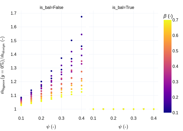
Figure 1. Bypass mass flow rate (ratio to design value) at fully
closed conditions as a function of ψ for various valve authorities
β (color scale), and a bypass branch either balanced (right plot)
or not (left plot).
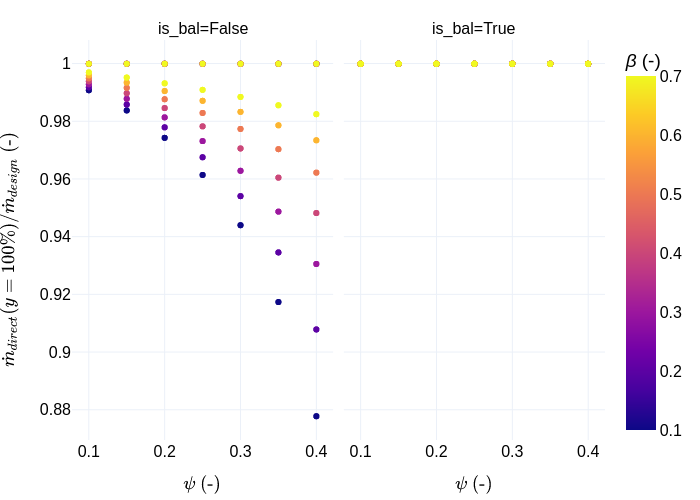
Figure 2. Direct mass flow rate (ratio to design value) at fully
open conditions as a function of ψ for various valve authorities β
(color scale), and a bypass branch either balanced (right plot) or
not (left plot).
The total primary mass flow rate (or pump mass flow rate) is plotted on Figure 3. This helps assess the actual flow variation in "constant flow circuits", i.e., constant speed pump distribution systems with terminal units equipped with three-way control valves. The total pump flow can vary up to 50% when the bypass of the three-way valves is not balanced, whereas the flow variation is limited to about 20% when the bypass of the three-way valves is balanced. If the characteristic of the valves is equal percentage and linear, this variation is rather by higher values for an unbalanced bypass and by lower values for a balanced bypass. If the characteristic of the valves is linear and linear, this variation is always by higher values. Eventually, when the control valve authority is higher than 0.5 the flow variation is limited to about ±20% in all cases.
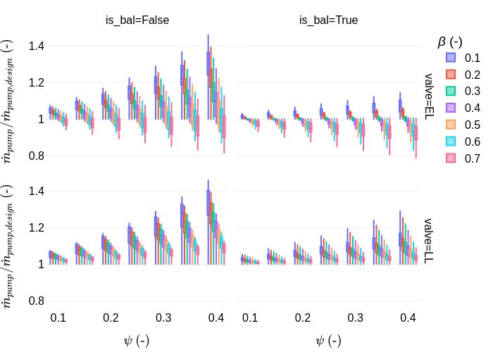
Figure 3. Pump mass flow rate (ratio to design value) as a
function of ψ for various valve authorities β (color scale), a
bypass branch either balanced (right plots) or not (left plots) and
either an equal-percentage / linear valve characteristic (top
plots) or a linear / linear valve characteristic (bottom
plots).
The heat flow rate transferred to the load is presented
The impact on the coil capacity of the flow shortage due to an unbalanced bypass is limited to about 5% and is less than 2% for an authority higher or equal to 0.5. A balanced bypass tends to disturb the linearity of the heat flow rate with the valve opening. But again, if the valve is selected with an authority higher or equal to 0.5 that disturbance is highly reduced.
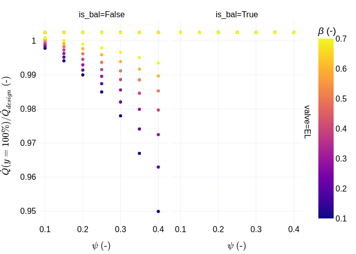
Figure 4. Heat flow rate (ratio to design value) at fully open
conditions as a function of ψ for various valve authorities β
(color scale), and a bypass branch either balanced (right plot) or
not (left plot).
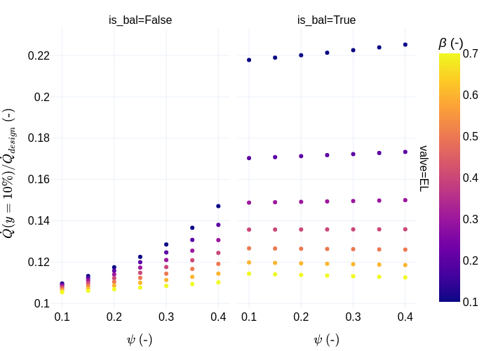
Figure 5. Heat flow rate (ratio to design value) at 10% open
conditions as a function of ψ for various valve authorities β
(color scale), and a bypass branch either balanced (right plot) or
not (left plot).