
modelSingleMixing
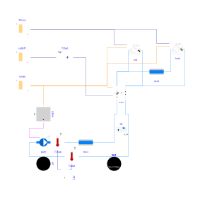
Extends from BaseClasses.PartialActivePrimary (Partial model of active primary network).
Information
This model represents a heating system where the configuration Buildings.Fluid.HydronicConfigurations.ActiveNetworks.SingleMixing serves as the interface between a variable flow primary circuit at constant supply temperature and a constant flow secondary circuit at variable supply temperature. The primary pump is operated at constant speed so the operating point rides the pump characteristic as the three-way valve closes. The secondary supply temperature is reset with an open loop, representing for instance a reset logic based on the outdoor air temperature. Two identical terminal units are served by the secondary circuit. Each terminal unit has its own hourly load profile.
For this model to simulate properly the ratio of the Kvs coefficient
between the bypass branch and the direct branch of the control valve
(con.val.fraK) must be set to 1.
Otherwise, if con.val.fraK=0.7 cavitation occurs when
the secondary pump starts and the
control valve is fully open, as the secondary pump head
exceeds the primary pressure differential augmented by the
pressure drop across the direct branch of the control valve.
Alternatively, if the pump is sized with the pressure drop across
the direct branch of the control valve (disregarding the higher
pressure drop across the bypass) it cannot provide enough head
at low supply temperature set point when the valve is partially closed.
Note that the load loa1 is not fully met at partial load
(see plot #4 from 17 h in model time) due to the unbalanced bypass
of the terminal unit control valves.
See
Buildings.Fluid.HydronicConfigurations.ActiveNetworks.Examples.DiversionOpenLoop
for further details.
Parameters
| Type | Name | Default | Description |
|---|---|---|---|
| Buildings.Fluid.HydronicConfigurations.Types.Control | typ (from PartialActivePrimary) | Buildings.Fluid.HydronicConfigurations.Types.Control.Heating | Load type |
| Integer | nTer (from PartialActivePrimary) | 2 | Number of terminal units |
| Real | kSizPum (from PartialActivePrimary) | 1.0 | Pump oversizing coefficient |
| Modelica.Units.SI.Pressure | p_min (from PartialActivePrimary) | 200000 | Circuit minimum pressure |
| Modelica.Units.SI.Temperature | TLiqEnt_nominal (from PartialActivePrimary) | if typ == Buildings.Fluid.HydronicConfigurations.Types.Control.Heating then 60 + 273.15 else 7 + 273.15 | Liquid entering temperature at design conditions |
| Modelica.Units.SI.Temperature | TLiqLvg_nominal (from PartialActivePrimary) | TLiqEnt_nominal + (if typ == Buildings.Fluid.HydronicConfigurations.Types.Control.Heating then -10 else +5) | Liquid leaving temperature at design conditions |
| Modelica.Units.SI.Temperature | TLiqEntChg_nominal (from PartialActivePrimary) | 60 + 273.15 | Liquid entering temperature in change-over mode |
| Modelica.Units.SI.Temperature | TLiqSup_nominal (from PartialActivePrimary) | TLiqEnt_nominal | Liquid primary supply temperature at design conditions |
| Modelica.Units.SI.Temperature | TLiqSupChg_nominal (from PartialActivePrimary) | TLiqEntChg_nominal | Liquid primary supply temperature in change-over mode |
| Nominal condition | |||
| Modelica.Units.SI.MassFlowRate | mTer_flow_nominal (from PartialActivePrimary) | 1 | Terminal unit mass flow rate at design conditions |
| Modelica.Units.SI.MassFlowRate | m1_flow_nominal (from PartialActivePrimary) | m2_flow_nominal | Mass flow rate in primary branch at design conditions |
| Modelica.Units.SI.MassFlowRate | m2_flow_nominal (from PartialActivePrimary) | nTer*mTer_flow_nominal | Mass flow rate in consumer circuit at design conditions |
| Modelica.Units.SI.PressureDifference | dpTer_nominal (from PartialActivePrimary) | 3E4 | Terminal unit pressure drop at design conditions |
| Modelica.Units.SI.PressureDifference | dpPip_nominal (from PartialActivePrimary) | 0.5E4 | Pipe section pressure drop at design conditions |
| Modelica.Units.SI.PressureDifference | dpPum_nominal (from PartialActivePrimary) | Pump head at design conditions | |
| Modelica.Units.SI.MassFlowRate | mPum_flow_nominal (from PartialActivePrimary) | m1_flow_nominal | Primary pump mass flow rate at design conditions |
| Dynamics › Conservation equations | |||
| Modelica.Fluid.Types.Dynamics | energyDynamics (from PartialActivePrimary) | Modelica.Fluid.Types.Dynamics.FixedInitial | Type of energy balance: dynamic (3 initialization options) or steady state |
| Configuration | |||
| Boolean | is_bal | true | Set to true for balanced primary branch |
Components
Revisions
-
June 30, 2022, by Antoine Gautier:
First implementation.