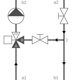
This configuration (see schematic below) is used for variable flow primary circuits and either constant flow or variable flow secondary circuits that have a design supply temperature identical to the primary circuit but a varying set point during operation.
The following table presents the main characteristics of this configuration.
| Primary circuit | Variable flow |
| Secondary (consumer) circuit | Constant or variable flow |
| Typical applications | Widely used in heating applications as it is very simple to achieve. |
| Non-recommended applications | Low-temperature systems that would require the control valve to be operated on a limited opening range: use Buildings.Fluid.HydronicConfigurations.PassiveNetworks.DualMixing instead. |
| Built-in valve control options | Supply temperature |
| Control valve selection (See the nomenclature in the schematic.) |
β = ΔpA-AB / (Δp1 +
ΔpA-AB) The control valve is sized with a pressure drop equal to the maximum of Δp1 and 3e3 Pa. |
| Balancing requirement | In most cases the bypass balancing valve is not needed. However, it may be needed to counter negative back pressure created by other served circuits, see Buildings.Fluid.HydronicConfigurations.PassiveNetworks.Examples.SingleMixingOpenLoop. |
| Lumped flow resistance includes (With the setting use_lumFloRes=true.) |
Control valve val and primary
balancing valve res1 |
The parameter dp1_nominal stands for the potential
primary back pressure and must be provided as an absolute value. By
default the secondary pump is parameterized with a design pressure
rise equal to dp2_nominal + dpBal2_nominal +
max({val.dpValve_nominal + dp1_nominal, val.dp3Valve_nominal +
dpBal3_nominal}.