
modelChimneyShaftNoVolume
Extends from Modelica.Icons.Example (Icon for runnable examples).
Information
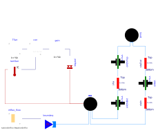
This model demonstrate buoyancy-induced air flow through a vertical shaft. On the right, there are two flow paths that are connected to a volume, which is kept at 20°C through a feedback controller, and to the ambient, which is at 0°C. The flow path on the very right consists of an orifice and two models that compute the pressure difference Δp between the bottom and top of the medium column using Δp=h ρ g, where h is the height of the medium column, ρ is the density of the medium column and g is the gravity constant.
The top model is parameterized to use the
density from the ambient,
whereas the bottom model is parameterized to use
the density from the room volume, regardless of
the flow direction.
In the other flow path, the model sha
is parameterized to use the density of the inflowing
medium.
Thus, these models can be thought of as a chimney to the left,
and a roof with a leakage on the right. The chimney height starts
1.5 m below the roof, and ends 1.5 m above the roof.
The flow boundary condition of the model
boundary is such that at the start
of the simulation, air flows from boundary
to roo until t=600 seconds. Then, the flow rate
is set to zero until t=1800 seconds.
Since the shaft sha is filled with
20°C air, there is a circulation in the clock-wise
direction; up the shaft, and down the other flow path.
Next, until t=2400 seconds, air is extracted from
the volume roo, and then the flow rate
of boundary is set to zero. Since the
shaft sha is now filed with air at 0°C,
there is a counter clock-wise flow; down the shaft, and
up the other flow path.
Components
| Type | Name | Default | Description |
|---|---|---|---|
| Buildings.Fluid.MixingVolumes.MixingVolume | roo | Air volume of a room | |
| Buildings.Airflow.Multizone.Orifice | oriChiTop | Orifice at top | |
| Buildings.Fluid.Sources.MassFlowSource_T | boundary | Mass flow rate boundary condition | |
| Buildings.Fluid.Sources.Boundary_pT | bou0 | Pressure boundary condition | |
| Buildings.Airflow.Multizone.Orifice | oriBot | Orifice | |
| Modelica.Blocks.Sources.CombiTimeTable | mRoo_flow | Mass flow into and out of room to fill the medium column with air of different temperature | |
| MediumColumn | staOut | Model for stack effect outside the room | |
| Buildings.Airflow.Multizone.Orifice | oriChiBot | Orifice at bottom | |
| Modelica.Thermal.HeatTransfer.Sources.PrescribedHeatFlow | preHea | Prescribed heat flow rate | |
| Modelica.Blocks.Continuous.LimPID | con | Controller to maintain volume temperature | |
| Modelica.Blocks.Sources.Constant | TSet | Temperature set point | |
| Modelica.Thermal.HeatTransfer.Sensors.TemperatureSensor | temSen | Temperature sensor | |
| Modelica.Blocks.Math.Gain | gain | Gain for heat flow rate | |
| Buildings.Airflow.Multizone.MediumColumn | sha | Shaft of chimney | |
| MediumColumn | staIn | Model for stack effect inside the room |
Contents
| Name | Description |
|---|---|
 Medium Medium |
Revisions
-
March 26, 2021 by Michael Wetter:
Updated comments for IBPSA, #515. -
February 24, 2015 by Michael Wetter:
Changed media to Modelica.Media.Air.SimpleAir in order to test the medium column for a media that has no moisture. -
December 22, 2014 by Michael Wetter:
RemovedModelica.Fluid.Systemto address issue #311. -
November 10, 2011, by Michael Wetter:
Added documentation.