
modelNonIntegratedPrimarySecondaryEconomizer
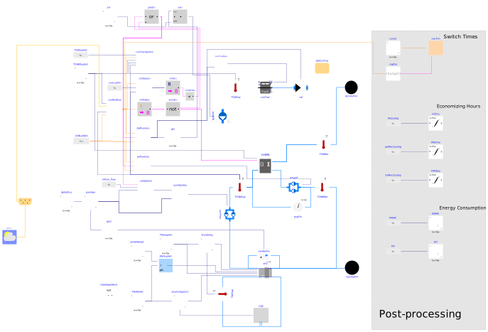
Extends from Modelica.Icons.Example (Icon for runnable examples), Buildings.Applications.DataCenters.ChillerCooled.Examples.BaseClasses.PostProcess (Post-processing), Buildings.Applications.DataCenters.ChillerCooled.Examples.BaseClasses.PartialDataCenter (Partial model that impliments cooling system for data centers).
Information
System Configuration
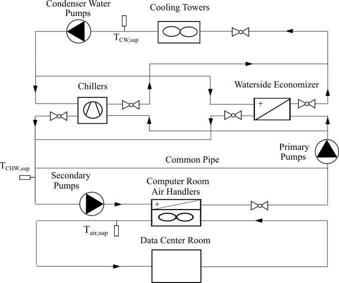
This example demonstrates the implementation of a chiller plant with water-side economizer (WSE) to cool a data center. The system schematics is as shown below.
The system is a primary-secondary chiller plant with two chillers and a non-integrated WSE.
Control Logic
This section describes the detailed control logic used in this chilled water plant system.
Cooling Mode Control
The chilled water system with non-integrated waterside economizer can run in two modes: free cooling (FC) mode, and fully mechanical cooling (FMC) mode. The detailed control logics about how to switch between these two cooling modes are described in Buildings.Applications.DataCenters.ChillerCooled.Controls.CoolingModeNonIntegrated. Details on how the valves are operated under different cooling modes are presented in Buildings.Applications.DataCenters.ChillerCooled.Equipment.NonIntegrated.
Chiller Staging Control
The staging sequence of multiple chillers are descibed as below:
- The chillers are all off when cooling mode is FC.
- One chiller is commanded on when cooling mode is not FC.
- Two chillers are commanded on when cooling mode is not FC and the cooling load addressed by chillers is larger than a critical value.
The detailed implementation is shown in Buildings.Applications.DataCenters.ChillerCooled.Controls.ChillerStage.
Pump Staging Control
For constant speed pumps, the number of running pumps equals to the number of running chillers.
For variable speed pumps, the number of runing pumps is controlled by the speed signal and the mass flowrate. Details are shown in Buildings.Applications.BaseClasses.Controls.VariableSpeedPumpStage. And the speed is controlled by maintaining a fixed differential pressure between the outlet and inlet on the waterside of the Computer Room Air Handler (CRAH).
Cooling Tower Speed Control
The control logic for cooling tower fan speed is described as:
- When in FMC mode, the cooling tower speed is controlled to maintain the condenser water supply temperature (CWST) at its setpoint.
- When in FC mode, the fan speed is modulated to maintain chilled water supply temperature at its setpoint.
Detailed implementation of cooling tower speed control can be found in Buildings.Applications.DataCenters.ChillerCooled.Controls.CoolingTowerSpeed.
Room temperature control
The room temperature is controlled by adjusting the fan speed of the AHU using a PI controller.
Note that for simplicity, the temperature and differential pressure reset control are not implemented in this example.
Parameters
| Type | Name | Default | Description |
|---|---|---|---|
| Integer | numChi (from PartialDataCenter) | 2 | Number of chillers |
| Modelica.Units.SI.MassFlowRate | m1_flow_chi_nominal (from PartialDataCenter) | 34.7 | Nominal mass flow rate at condenser water in the chillers |
| Modelica.Units.SI.MassFlowRate | m2_flow_chi_nominal (from PartialDataCenter) | 18.3 | Nominal mass flow rate at evaporator water in the chillers |
| Modelica.Units.SI.PressureDifference | dp1_chi_nominal (from PartialDataCenter) | 46.2*1000 | Nominal pressure |
| Modelica.Units.SI.PressureDifference | dp2_chi_nominal (from PartialDataCenter) | 44.8*1000 | Nominal pressure |
| Modelica.Units.SI.Power | QEva_nominal (from PartialDataCenter) | m2_flow_chi_nominal*4200*(6.67 - 18.56) | Nominal cooling capaciaty(Negative means cooling) |
| Modelica.Units.SI.MassFlowRate | m1_flow_wse_nominal (from PartialDataCenter) | 34.7 | Nominal mass flow rate at condenser water in the chillers |
| Modelica.Units.SI.MassFlowRate | m2_flow_wse_nominal (from PartialDataCenter) | 35.3 | Nominal mass flow rate at condenser water in the chillers |
| Modelica.Units.SI.PressureDifference | dp1_wse_nominal (from PartialDataCenter) | 33.1*1000 | Nominal pressure |
| Modelica.Units.SI.PressureDifference | dp2_wse_nominal (from PartialDataCenter) | 34.5*1000 | Nominal pressure |
| Buildings.Fluid.Movers.Data.Generic | perPumCW (from PartialDataCenter) | Performance data for condenser water pumps | |
| Modelica.Units.SI.Time | tWai (from PartialDataCenter) | 1200 | Waiting time |
| Modelica.Units.SI.ThermalConductance | UA_nominal (from PartialDataCenter) | numChi*QEva_nominal/Buildings.Fluid.HeatExchangers.BaseClasses.lmtd(6.67, 11.56, 12, 25) | Thermal conductance at nominal flow for sensible heat, used to compute time constant |
| Modelica.Units.SI.MassFlowRate | mAir_flow_nominal (from PartialDataCenter) | 161.35 | Nominal air mass flowrate |
| Real | yValMinAHU (from PartialDataCenter) | 0.1 | Minimum valve openning position |
| Modelica.Units.SI.Temperature | TCHWSet (from PartialDataCenter) | 273.15 + 8 | Chilled water temperature setpoint |
| Modelica.Units.SI.Temperature | TSupAirSet (from PartialDataCenter) | TCHWSet + 10 | Supply air temperature setpoint |
| Modelica.Units.SI.Temperature | TRetAirSet (from PartialDataCenter) | 273.15 + 25 | Supply air temperature setpoint |
| Modelica.Units.SI.Pressure | dpSetPoi (from PartialDataCenter) | 80000 | Differential pressure setpoint |
| Fluid.HeatExchangers.CoolingTowers.Data.YorkCalc.Generic | datCooTow (from PartialDataCenter) | Cooling tower performance data | |
| Buildings.Fluid.Movers.Data.Generic | perPumSec | Performance data for secondary chilled water pumps | |
| Buildings.Fluid.Movers.Data.Generic | perPumPri | Performance data for secondary chilled water pumps |
Connectors
| Type | Name | Default | Description |
|---|---|---|---|
| Buildings.BoundaryConditions.WeatherData.Bus | weaBus (from PartialDataCenter) | Weather data bus |
Components
Revisions
-
September 3, 2024, by Jianjun Hu:
Added plant on signal to control the pump speed. This is for issue 3989. -
November 16, 2022, by Michael Wetter:
Corrected control to avoid cooling tower pumps to operate when plant is off, because shut-off valves are off when plant is off. -
November 1, 2021, by Michael Wetter:
Corrected weather data bus connection which was structurally incorrect and did not parse in OpenModelica.
This is for issue 2706. -
December 1, 2017, by Yangyang Fu:
Removed redundant connectionconnect(dpSet.y, pumSpe.u_s) -
November 29, 2017, by Michael Wetter:
Corrected conversion of enumeration.
This is for issue 1083. -
July 30, 2017, by Yangyang Fu:
First implementation.