
modelDXCooledAirsideEconomizer
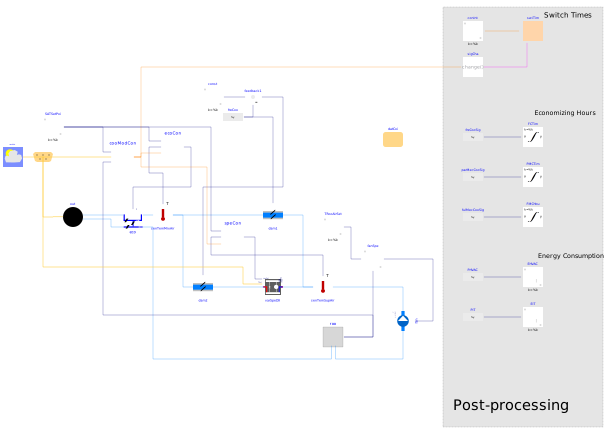
Extends from Modelica.Icons.Example (Icon for runnable examples), Buildings.Applications.DataCenters.ChillerCooled.Examples.BaseClasses.PostProcess (Post-processing).
Information
This example illustrates how to use Buildings.Fluid.DXSystems.Cooling.AirSource.VariableSpeed in a cooling system for data center rooms.
System description
A air-cooled direct expansion (DX) cooling system with an airside economizer is used for a data center room. For simplicity, the data center room has a constant cooling load. The DX cooling system includes a variable-speed compressor, a cooling coil and a variable speed fun. The airside economizer is located before DX package to pre-cool the mixed air.
Control logic
Cooling mode control
This system can run in three cooling modes: free cooling (FC) mode, partially mechanical cooling (PMC) mode and fully mechanical cooling (FMC) mode.In FC mode, only the airside economizer is commanded to run. The supply air temperature is maintained by adjusting the outdoor air damper. In PMC mode, the airside economizer and the DX cooling coil are commanded to run together. And in FMC mode, only the DX cooling coil is commanded to run. To avoid frequent switching, a deadband of 1 Kelvin and a waiting time of 120 s are used.
A demonstration on how to switch among these three cooling modes is shown in Buildings.Applications.DataCenters.DXCooled.Controls.Validation.CoolingMode.
Supply air temperature control
In FC mode, the supply air temperature is controlled by adjusting outdoor air damper. In PMC mode, the outdoor air damper is fully open, and the speed of compressor in the DX unit can be adjusted to maintain the supply air temperature. In FMC mode, the outdoor air damper is fully closed and the supply air temperature is maintained by manipulating the compressor speed. In this case, the supply air temperature setpoint is set as 18 °C.
Room temperature control
The room temperature is maintained at 24°C by adjusting the speed of the supply air fan.
Parameters
| Type | Name | Default | Description |
|---|---|---|---|
| Modelica.Units.SI.Temperature | TASup_nominal | 286.15 | Nominal air temperature supplied to room |
| Modelica.Units.SI.Temperature | TRooSet | 298.15 | Nominal room air temperature |
| Modelica.Units.SI.Temperature | TAirSupSet | 291.13 | Nominal room air temperature |
| Modelica.Units.SI.HeatFlowRate | QRooInt_flow | 500000 | Internal heat gains of the room |
| Modelica.Units.SI.HeatFlowRate | QRooC_flow_nominal | -2*QRooInt_flow | |
| Modelica.Units.SI.MassFlowRate | mA_flow_nominal | QRooC_flow_nominal/1006/(TASup_nominal - TRooSet) | Nominal air mass flow rate |
| Modelica.Units.SI.HeatFlowRate | QCoiC_flow_nominal | QRooC_flow_nominal | Cooling load of coil |
| Real | minSpeFan | 0.2 | Minimum fan speed ratio required by variable speed fans |
| Buildings.Fluid.DXSystems.Cooling.AirSource.Data.Generic.DXCoil | datCoi | Coil data |
Connectors
| Type | Name | Default | Description |
|---|---|---|---|
| Buildings.BoundaryConditions.WeatherData.Bus | weaBus | Weather data bus |
Components
Contents
| Name | Description |
|---|---|
 Medium Medium | Medium model |
Revisions
-
April 4, 2023, by Karthik Devaprasad:
Updated classes used in the coil data recorddatCoias per the changed class names.
Updated class used for variable speed DX cooling coilvarSpeDX. -
August 16, 2017 by Yangyang Fu:
First implementation.