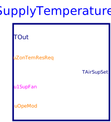
blockSupplyTemperature
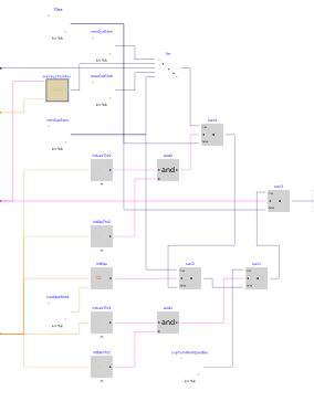
Information
Block that outputs the supply air temperature setpoint and the coil valve control inputs for VAV system with multiple zones, implemented according to Section 5.16.2 of the ASHRAE Guideline G36, May 2020.
The control loop is enabled when the supply air fan u1SupFan is proven on,
and disabled and the output set to deadband (no heating, minimum economizer) otherwise.
The supply air temperature setpoint is computed as follows.
Setpoints for TSupCoo_min, TSupCoo_max,
TOut_min, TOut_max
Per Section 3.1.4.1, the setpoints are design information.
-
The
TSupCoo_minshould be set no lower than the design coil leaving air temperature to prevent excessive chilled water temperature reset requests. -
The
TSupCoo_maxis typically 18 °C (65 °F) in mild and dry climates and 16 °C (60 °F) or lower in humid climates. It should not typically be greater than 18 °C (65 °F). -
The default range of outdoor air temperature (
TOut_min=16°C,TOut_max=21°C) used to reset the occupied modeTSupSetwas chosen to maximize economizer hours. It may be preferable to use a lower range of outdoor air temperature (e.g.TOut_min=13°C,TOut_max=18°C) to minimize fan energy.
During occupied and Setup modes (uOpeMod=1, uOpeMod=2)
The TSupSet shall be reset from TSupCoo_min when the outdoor
air temperature is TOut_max and above, proportionally up to
maximum supply temperature when the outdoor air temperature is TOut_min and
below. The maximum supply temperature shall be reset using trim and respond logic between
TSupCoo_min and TSupCoo_max. Parameters suggested for the
trim and respond logic are shown in the table below. They require adjustment
during the commissioning and tuning phase.
| Variable | Value | Definition |
|---|---|---|
| Device | AHU Supply Fan | Associated device |
| SP0 | iniSet | Initial setpoint |
| SPmin | TSupCoo_min | Minimum setpoint |
| SPmax | TSupCoo_max | Maximum setpoint |
| Td | delTim | Delay timer |
| T | samplePeriod | Time step |
| I | numIgnReq | Number of ignored requests |
| R | uZonTemResReq | Number of requests |
| SPtrim | triAmo | Trim amount |
| SPres | resAmo | Respond amount |
| SPres_max | maxRes | Maximum response per time interval |

During Cool-down modes (uOpeMod=3)
Supply air temperature setpoint TSupSet shall be TSupCoo_min.
During Setback and Warmup modes (uOpeMod=4, uOpeMod=5)
Supply air temperature setpoint TSupSet shall be TSupWarUpSetBac.
Parameters
| Type | Name | Default | Description |
|---|---|---|---|
| Temperatures | |||
| Real | TSupCoo_min | 285.15 | Lowest cooling supply air temperature setpoint when the outdoor air temperature is at the higher value of the reset range and above |
| Real | TSupCoo_max | 291.15 | Highest cooling supply air temperature setpoint. It is typically 18 degC (65 degF) in mild and dry climates, 16 degC (60 degF) or lower in humid climates |
| Real | TOut_min | 289.15 | Lower value of the outdoor air temperature reset range. Typically value is 16 degC (60 degF) |
| Real | TOut_max | 294.15 | Higher value of the outdoor air temperature reset range. Typically value is 21 degC (70 degF) |
| Real | TSupWarUpSetBac | 308.15 | Supply temperature in warm up and set back mode |
| Trim and respond logic | |||
| Real | delTim | 600 | Delay timer |
| Real | samplePeriod | 120 | Sample period of component |
| Integer | numIgnReq | 2 | Number of ignorable requests for TrimResponse logic |
| Real | triAmo | 0.1 | Trim amount |
| Real | resAmo | -0.2 | Response amount |
| Real | maxRes | -0.6 | Maximum response per time interval |
Connectors
| Type | Name | Default | Description |
|---|---|---|---|
| Buildings.Controls.OBC.CDL.Interfaces.RealInput | TOut | Outdoor air temperature | |
| Buildings.Controls.OBC.CDL.Interfaces.BooleanInput | u1SupFan | Supply fan status | |
| Buildings.Controls.OBC.CDL.Interfaces.IntegerInput | uOpeMod | System operation mode | |
| Buildings.Controls.OBC.CDL.Interfaces.IntegerInput | uZonTemResReq | Zone cooling supply air temperature reset request | |
| Buildings.Controls.OBC.CDL.Interfaces.RealOutput | TAirSupSet | Supply air temperature setpoint |
Components
| Type | Name | Default | Description |
|---|---|---|---|
| Buildings.Controls.OBC.ASHRAE.G36.Generic.TrimAndRespond | maxSupTemRes | Maximum cooling supply temperature reset |
Revisions
-
August 1, 2020, by Jianjun Hu:
First implementation.