blockController
Information
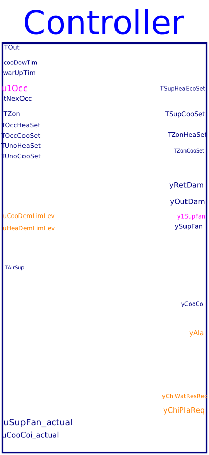
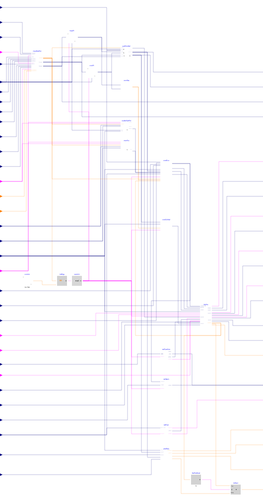
Block for single zone VAV control. It outputs supply fan speed, supply air temperature setpoints for heating, economizer and cooling, zone air heating and cooling setpoints, outdoor and return air damper positions, and valve positions of heating and cooling coils. It is implemented according to the ASHRAE Guideline 36, Section 5.18.
The sequences consist of the following subsequences.
Supply fan speed control
The fan speed control is implemented according to Section 5.18.4. It outputs
the control signal yFan to adjust the speed of the supply fan.
See
Buildings.Controls.OBC.ASHRAE.G36.AHUs.SingleZone.VAV.SetPoints.Supply
for more detailed description.
Supply air temperature setpoints
The supply air temperature setpoints control sequences are implemented based on Section 5.18.4. They are implemented in the same control block as the supply fan speed control. The supply air temperature setpoint for heating and economizer is the same; while the supply air temperature setpoint for cooling has a separate control loop. See Buildings.Controls.OBC.ASHRAE.G36.AHUs.SingleZone.VAV.SetPoints.Supply for more detailed description.
Economizer control
The Economizer control block outputs outdoor and return air damper position, i.e. yOutDamPos and
yRetDamPos, as well as control signal for heating coil yHeaCoi.
See
Buildings.Controls.OBC.ASHRAE.G36.AHUs.SingleZone.VAV.Economizers.Controller
for more detailed description.
Minimum outdoor airflow
Control sequences are implemented to compute the minimum outdoor airflow setpoint, which is used as an input for the economizer control. More detailed information can be found at Buildings.Controls.OBC.ASHRAE.G36.VentilationZones.ASHRAE62_1.Setpoints.
Zone air heating and cooling setpoints
Zone air heating and cooling setpoints as well as system operation modes are detailed at Buildings.Controls.OBC.ASHRAE.G36.AHUs.SingleZone.VAV.SetPoints.ModeAndSetPoints.
Coil valve control
The subsequence retrieves supply air temperature setpoint from previous sequence. Along with the measured supply air temperature and the supply fan status, it generates coil valve positions. See Buildings.Controls.OBC.ASHRAE.G36.AHUs.SingleZone.VAV.SetPoints.CoolingCoil for more detailed description.
Freeze protection
Based on the Section 5.18.11, the sequence enables freeze protection if the measured supply air temperature belows certain thresholds. There are three protection stages. See Buildings.Controls.OBC.ASHRAE.G36.AHUs.SingleZone.VAV.SetPoints.FreezeProtection for more detailed description.
Building pressure control
By selecting different building pressure control designs, which includes using actuated relief dampers without fans, using actuated relief dampers with relief fan, using return fans. See belows sequences for more detailed description:
- Buildings.Controls.OBC.ASHRAE.G36.AHUs.SingleZone.VAV.SetPoints.ReliefDamper
- Relief fan control Buildings.Controls.OBC.ASHRAE.G36.AHUs.SingleZone.VAV.SetPoints.ReliefFan is not included in the AHU controller. This sequence controls all the relief fans that are serving one common space, which may include multiple air handling units.
- Buildings.Controls.OBC.ASHRAE.G36.AHUs.SingleZone.VAV.SetPoints.ReturnFan
Plant request
According to the Section 5.18.15, the sequence send out heating or cooling plant requests if the supply air temperature is below or above threshold value, or the heating or cooling valves have been widely open for certain times. See Buildings.Controls.OBC.ASHRAE.G36.AHUs.SingleZone.VAV.SetPoints.PlantRequests for more detailed description.
Parameters
| Type | Name | Default | Description |
|---|---|---|---|
| Buildings.Controls.OBC.ASHRAE.G36.Types.EnergyStandard | eneStd | Energy standard, ASHRAE 90.1 or Title 24 | |
| Buildings.Controls.OBC.ASHRAE.G36.Types.VentilationStandard | venStd | Ventilation standard, ASHRAE 62.1 or Title 24 | |
| Buildings.Controls.OBC.ASHRAE.G36.Types.ControlEconomizer | ecoHigLimCon | Buildings.Controls.OBC.ASHRAE.G36.Types.ControlEconomizer.FixedDryBulb | Economizer high limit control device |
| Buildings.Controls.OBC.ASHRAE.G36.Types.ASHRAEClimateZone | ashCliZon | Buildings.Controls.OBC.ASHRAE.G36.Types.ASHRAEClimateZone.Not_Specified | ASHRAE climate zone |
| Buildings.Controls.OBC.ASHRAE.G36.Types.Title24ClimateZone | tit24CliZon | Buildings.Controls.OBC.ASHRAE.G36.Types.Title24ClimateZone.Not_Specified | California Title 24 climate zone |
| Boolean | have_frePro | true | True: enable freeze protection |
| Buildings.Controls.OBC.ASHRAE.G36.Types.FreezeStat | freSta | Buildings.Controls.OBC.ASHRAE.G36.Types.FreezeStat.No_freeze_stat | Type of freeze stat |
| Boolean | have_winSen | false | Check if the zone has window status sensor |
| Boolean | have_occSen | false | Check if the zone has occupancy sensor |
| Buildings.Controls.OBC.ASHRAE.G36.Types.CoolingCoil | cooCoi | Buildings.Controls.OBC.ASHRAE.G36.Types.CoolingCoil.WaterBased | Cooling coil type |
| Buildings.Controls.OBC.ASHRAE.G36.Types.HeatingCoil | heaCoi | Buildings.Controls.OBC.ASHRAE.G36.Types.HeatingCoil.WaterBased | Heating coil type |
| Boolean | have_CO2Sen | true | True: the zone has CO2 sensor |
| Buildings.Controls.OBC.ASHRAE.G36.Types.PressureControl | buiPreCon | Buildings.Controls.OBC.ASHRAE.G36.Types.PressureControl.BarometricRelief | Type of building pressure control system |
| Boolean | have_ahuRelFan | true | True: relief fan is part of AHU; False: the relief fans group that may associate multiple AHUs |
| Design conditions | |||
| Real | VAreBreZon_flow | 0 | Design area component of the breathing zone outdoor airflow |
| Real | VPopBreZon_flow | 0 | Design population component of the breathing zone outdoor airflow |
| Setpoints adjustment › Adjustable settings | |||
| Boolean | have_locAdj | true | True: the zone has local setpoint adjustment knob |
| Boolean | sepAdj | true | True: cooling and heating setpoint can be adjusted separately |
| Boolean | ignDemLim | true | Flag, set to true to exempt individual zone from demand limit setpoint adjustment |
| Setpoints adjustment › Limits | |||
| Real | TActCoo_max | 300.15 | Maximum cooling setpoint during on |
| Real | TActCoo_min | 295.15 | Minimum cooling setpoint during on |
| Real | TActHea_max | 295.15 | Maximum heating setpoint during on |
| Real | TActHea_min | 291.15 | Minimum heating setpoint during on |
| Real | TWinOpeCooSet | 322.15 | Cooling setpoint when window is open |
| Real | TWinOpeHeaSet | 277.15 | Heating setpoint when window is open |
| Setpoints adjustment › Demand control adjustment | |||
| Real | incTSetDem_1 | 0.5 | Cooling setpoint increase value (degC) when cooling demand limit level 1 is imposed |
| Real | incTSetDem_2 | 1 | Cooling setpoint increase value (degC) when cooling demand limit level 2 is imposed |
| Real | incTSetDem_3 | 2 | Cooling setpoint increase value (degC) when cooling demand limit level 3 is imposed |
| Real | decTSetDem_1 | 0.5 | Heating setpoint decrease value (degC) when heating demand limit level 1 is imposed |
| Real | decTSetDem_2 | 1 | Heating setpoint decrease value (degC) when heating demand limit level 2 is imposed |
| Real | decTSetDem_3 | 2 | Heating setpoint decrease value (degC) when heating demand limit level 3 is imposed |
| Setpoints adjustment › Operation mode | |||
| Real | preWarCooTim | 10800 | Maximum cool-down or warm-up time |
| Real | TZonFreProOn | 277.15 | Threshold temperature to activate the freeze protection mode |
| Real | TZonFreProOff | 280.15 | Threshold temperature to end the freeze protection mode |
| Setpoints adjustment › Hysteresis | |||
| Real | bouLim | 1 | Threshold of temperature difference for indicating the end of setback or setup mode |
| Real | uLow | -0.1 | Low limit of the hysteresis for checking temperature difference |
| Real | uHigh | 0.1 | High limit of the hysteresis for checking temperature difference |
| Loops control › Cooling loop | |||
| Buildings.Controls.OBC.CDL.Types.SimpleController | cooLooCon | Buildings.Controls.OBC.CDL.Types.SimpleController.PI | Cooling loop controller type |
| Real | kCoo | 0.1 | Gain for cooling control loop signal |
| Real | TiCoo | 900 | Time constant of integrator block for cooling control loop signal |
| Real | TdCoo | 0.1 | Time constant of derivative block for cooling control loop signal |
| Loops control › Heating loop | |||
| Buildings.Controls.OBC.CDL.Types.SimpleController | heaLooCon | Buildings.Controls.OBC.CDL.Types.SimpleController.PI | Heating loop controller type |
| Real | kHea | 0.1 | Gain for heating control loop signal |
| Real | TiHea | 900 | Time constant of integrator block for heating control loop signal |
| Real | TdHea | 0.1 | Time constant of derivative block for heating control loop signal |
| Supply setpoints › Temperature | |||
| Real | TSup_max | 303.15 | Maximum supply air temperature for heating |
| Real | TSup_min | 291.15 | Minimum supply air temperature for cooling |
| Real | TSupDew_max | 290.15 | Maximum supply air dew-point temperature. It's typically only needed in humid type “A” climates. A typical value is 17°C. For mild and dry climates, a high set point (e.g. 24°C) should be entered for maximum efficiency |
| Real | TSupDea_min | 294.15 | Minimum supply temperature when it is in deadband state |
| Real | TSupDea_max | 297.15 | Maximum supply temperature when it is in deadband state |
| Real | temPoiOne | 0.5 | Point 1 on x-axis of control map for temperature control, when it is in heating state |
| Real | temPoiTwo | 0.25 | Point 2 on x-axis of control map for temperature control, when it is in cooling state |
| Real | temPoiThr | 0.5 | Point 3 on x-axis of control map for temperature control, when it is in cooling state |
| Real | temPoiFou | 0.75 | Point 4 on x-axis of control map for temperature control, when it is in cooling state |
| Supply setpoints › Fan speed | |||
| Real | maxHeaSpe | 1 | Maximum fan speed for heating |
| Real | maxCooSpe | 1 | Maximum fan speed for cooling |
| Real | minSpe | 0.1 | Minimum fan speed |
| Real | spePoiOne | 0.5 | Point 1 on x-axis of control map for speed control, when it is in heating state |
| Real | spePoiTwo | 0.25 | Point 2 on x-axis of control map for speed control, when it is in cooling state |
| Real | spePoiThr | 0.5 | Point 3 on x-axis of control map for speed control, when it is in cooling state |
| Real | spePoiFou | 0.75 | Point 4 on x-axis of control map for speed control, when it is in cooling state |
| Supply setpoints › Hysteresis | |||
| Real | looHys | 0.05 | Loop output hysteresis below which the output will be seen as zero |
| Outdoor airflow › ASHRAE62.1 | |||
| Boolean | permit_occStandby | true | True: occupied-standby mode is permitted |
| Real | zonDisEff_cool | 1.0 | Zone cooling air distribution effectiveness |
| Real | zonDisEff_heat | 0.8 | Zone heating air distribution effectiveness |
| Outdoor airflow › Title 24 | |||
| Real | VOccMin_flow | 0 | Zone minimum outdoor airflow for occupants |
| Real | VAreMin_flow | 0 | Zone minimum outdoor airflow for building area |
| Real | VZonMin_flow | 0 | Design zone minimum airflow setpoint |
| Economizer | |||
| Real | uMin | 0.1 | Lower limit of controller output at which the dampers are at their limits |
| Real | uMax | 0.9 | Upper limit of controller output at which the dampers are at their limits |
| Economizer › Modulation | |||
| Buildings.Controls.OBC.CDL.Types.SimpleController | ecoModCon | Buildings.Controls.OBC.CDL.Types.SimpleController.PI | Type of controller |
| Real | kMod | 1 | Gain of modulation controller |
| Real | TiMod | 300 | Time constant of modulation controller integrator block |
| Real | TdMod | 0.1 | Time constant of derivative block for modulation controller |
| Economizer › Commissioning | |||
| Real | supFanSpe_min | 0.1 | Minimum supply fan operation speed |
| Real | supFanSpe_max | 0.9 | Maximum supply fan operation speed |
| Real | VOutMin_flow | 1.0 | Calculated minimum outdoor airflow rate |
| Real | VOutDes_flow | 2.0 | Calculated design outdoor airflow rate |
| Real | outDamMinFloMinSpe | 0.4 | Outdoor air damper position to supply minimum outdoor airflow at minimum fan speed |
| Real | outDamMinFloMaxSpe | 0.3 | Outdoor air damper position to supply minimum outdoor airflow at maximum fan speed |
| Real | outDamDesFloMinSpe | 0.9 | Outdoor air damper position to supply design outdoor airflow at minimum fan speed |
| Real | outDamDesFloMaxSpe | 0.8 | Outdoor air damper position to supply design outdoor airflow at maximum fan speed |
| Real | outDamPhy_max | 1.0 | Physically fixed maximum position of the outdoor air damper |
| Real | outDamPhy_min | 0.0 | Physically fixed minimum position of the outdoor air damper |
| Real | retDamPhy_max | 1.0 | Physically fixed maximum position of the return air damper |
| Real | retDamPhy_min | 0.0 | Physically fixed minimum position of the return air damper |
| Economizer › Hysteresis | |||
| Real | delTOutHys | 1 | Delta between the temperature hysteresis high and low limit |
| Cooling coil | |||
| Buildings.Controls.OBC.CDL.Types.SimpleController | cooCoiCon | Buildings.Controls.OBC.CDL.Types.SimpleController.PI | Type of controller |
| Real | kCooCoi | 0.1 | Gain for cooling coil control loop signal |
| Real | TiCooCoi | 900 | Time constant of integrator block for cooling coil control loop signal |
| Real | TdCooCoi | 0.1 | Time constant of derivative block for cooling coil control loop signal |
| Freeze protection | |||
| Integer | minHotWatReq | 2 | Minimum heating hot-water plant request to active the heating plant |
| Freeze protection › Heating coil control | |||
| Buildings.Controls.OBC.CDL.Types.SimpleController | freHeaCoiCon | Buildings.Controls.OBC.CDL.Types.SimpleController.PI | Heating coil controller |
| Real | kFreHea | 1 | Gain of coil controller |
| Real | TiFreHea | 0.5 | Time constant of integrator block |
| Real | TdFreHea | 0.1 | Time constant of derivative block |
| Real | yMaxFreHea | 1 | Upper limit of output |
| Real | yMinFreHea | 0 | Lower limit of output |
| Pressure control › Relief damper | |||
| Real | relDam_min | 0.1 | Relief-damper position that maintains a building pressure of 12 Pa while the economizer damper is positioned to provide minimum outdoor air while the supply fan is at minimum speed |
| Real | relDam_max | 1 | Relief-damper position that maintains a building pressure of 12 Pa while the economizer damper is fully open and the fan speed is at cooling maximum |
| Pressure control › Return fan | |||
| Real | speDif | -0.1 | Speed difference between supply and return fan to maintain building pressure at desired pressure |
| Pressure control | |||
| Real | dpBuiSet | 12 | Building static pressure difference relative to ambient (positive to pressurize the building) |
| Pressure control › Relief fan | |||
| Real | relFanSpe_min | 0.1 | Relief fan minimum speed |
| Real | kRelFan | 1 | Gain of relief fan controller, normalized using dpBuiSet |
| Advanced › Hysteresis | |||
| Real | posHys | 0.01 | Hysteresis for damper position check |
| Real | THys | 0.25 | Hysteresis for checking temperature difference |
| Real | delEntHys | 1000 | Delta between the enthalpy hysteresis high and low limits |
| Real | floHys | 0.01*VOutMin_flow | Near zero flow rate, below which the flow rate or difference will be seen as zero |
Connectors
Components
Revisions
-
September 26, 2025, by Jianjun Hu:
Renamed the parameterThystoTHys.
This is for issue 4374. -
September 18, 2023, by Jianjun Hu:
Added coil type enumeration so to avoid using flag parameters.
This is for issue 3526. -
March 1, 2023, by Michael Wetter:
Changed constants from0to0.0and1to1.0.
This is for #3267. -
August 1, 2020, by Jianjun Hu:
First implementation.