blockSupply
Information
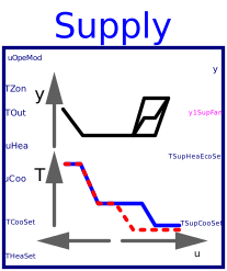
Block that outputs the set points for the supply air temperature for cooling, heating and economizer control, and the fan speed for a single zone VAV system. The implementation is according to the Section 5.18.4 of ASHRAE Guideline 36, May 2020.
Fan speed setpoint
The speed setpoint is calculated in Buildings.Controls.OBC.ASHRAE.G36.AHUs.SingleZone.VAV.SetPoints.SupplyFan. The supply fan shall run whenever the unit is in any mode other than unoccupied mode. Also, a ramp function should be applied to prevent changes in fan speed of more than 10% per minute.
Supply temperature setpoints
The output TSupCooSet is to be used to control the cooling coil,
and the output
TSupHeaEcoSet is to be used to control the heating coil and the
economizer dampers.
When it is in deadband state, the output TSupCooSet and TSupHeaEcoSet
shall be average of the zone heating setpoint THeaSet and the zone
cooling setpoint TCooSet but shall be no lower than TSupDea_min,
21 °C (70 °F),
and no higher than TSupDea_max, 24 °C (75 °F).
The temperature setpoints are calculated in
Buildings.Controls.OBC.ASHRAE.G36.AHUs.SingleZone.VAV.SetPoints.SupplyTemperature.
Note that the inputs uHea and uCoo must be computed
based on the same temperature sensors and control loops.
Parameters
| Type | Name | Default | Description |
|---|---|---|---|
| Temperatures | |||
| Real | TSup_max | Maximum supply air temperature for heating | |
| Real | TSup_min | Minimum supply air temperature for cooling | |
| Real | TSupDew_max | Maximum supply air dew-point temperature. It's typically only needed in humid type “A” climates. A typical value is 17°C. For mild and dry climates, a high set point (e.g. 24°C) should be entered for maximum efficiency | |
| Real | TSupDea_min | 294.15 | Minimum supply temperature when it is in deadband state |
| Real | TSupDea_max | 297.15 | Maximum supply temperature when it is in deadband state |
| Speed | |||
| Real | maxHeaSpe | Maximum fan speed for heating | |
| Real | maxCooSpe | Maximum fan speed for cooling | |
| Real | minSpe | Minimum fan speed | |
| Advanced › Temperatures | |||
| Real | temPoiOne | 0.5 | Point 1 on x-axis of control map for temperature control, when it is in heating state |
| Real | temPoiTwo | 0.25 | Point 2 on x-axis of control map for temperature control, when it is in cooling state |
| Real | temPoiThr | 0.5 | Point 3 on x-axis of control map for temperature control, when it is in cooling state |
| Real | temPoiFou | 0.75 | Point 4 on x-axis of control map for temperature control, when it is in cooling state |
| Advanced › Speed | |||
| Real | spePoiOne | 0.5 | Point 1 on x-axis of control map for speed control, when it is in heating state |
| Real | spePoiTwo | 0.25 | Point 2 on x-axis of control map for speed control, when it is in cooling state |
| Real | spePoiThr | 0.5 | Point 3 on x-axis of control map for speed control, when it is in cooling state |
| Real | spePoiFou | 0.75 | Point 4 on x-axis of control map for speed control, when it is in cooling state |
Connectors
| Type | Name | Default | Description |
|---|---|---|---|
| Buildings.Controls.OBC.CDL.Interfaces.IntegerInput | uOpeMod | AHU operation mode status signal | |
| Buildings.Controls.OBC.CDL.Interfaces.RealInput | TZon | Zone temperature | |
| Buildings.Controls.OBC.CDL.Interfaces.RealInput | TOut | Outdoor air temperature | |
| Buildings.Controls.OBC.CDL.Interfaces.RealInput | uHea | Heating control signal | |
| Buildings.Controls.OBC.CDL.Interfaces.RealInput | uCoo | Cooling control signal | |
| Buildings.Controls.OBC.CDL.Interfaces.RealInput | TCooSet | Cooling setpoints for zone temperature | |
| Buildings.Controls.OBC.CDL.Interfaces.RealInput | THeaSet | Heating setpoints for zone temperature | |
| Buildings.Controls.OBC.CDL.Interfaces.RealOutput | y | Fan speed | |
| Buildings.Controls.OBC.CDL.Interfaces.BooleanOutput | y1SupFan | Supply fan commanded status | |
| Buildings.Controls.OBC.CDL.Interfaces.RealOutput | TSupHeaEcoSet | Temperature setpoint for heating coil and for economizer | |
| Buildings.Controls.OBC.CDL.Interfaces.RealOutput | TSupCooSet | Cooling supply air temperature setpoint |
Revisions
-
June 30, 2025, by Jianjun Hu:
Improved setpoints calculation to avoid discontinuity. This is for issue 4282. -
August 1, 2020, by Jianjun Hu:
First implementation.