blockModulation
Information
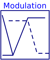
This is a single zone VAV AHU economizer modulation block. It calculates the outdoor and return air damper positions based on the single zone VAV AHU supply air temperature control loop signal. Economizer dampers are modulated based on the calculated heating supply air temperature setpoint. The implementation is in line with Section 5.18.5.1 and 5.18.5.2 of ASHRAE Guidline 36, May 2020. Damper positions are linearly mapped to the supply air control loop signal. This is a final sequence in the composite single zone VAV AHU economizer control sequence. Damper position limits, which are the inputs to the sequence, are the outputs of Buildings.Controls.OBC.ASHRAE.G36.AHUs.SingleZone.VAV.Economizers.Subsequences.Limits and Buildings.Controls.OBC.ASHRAE.G36.AHUs.SingleZone.VAV.Economizers.Subsequences.Enable sequences.
When the economizer is enabled, the PI controller modulates the damper positions. Return and outdoor damper are not interlocked. When the economizer is disabled, the damper positions are set to the minimum outdoor air damper position limits.
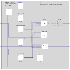
The figures below show the input-output structure and an economizer damper modulation sequence assuming a well configured controller.
Control diagram:

Single zone AHU economizer modulation control chart:

Parameters
| Type | Name | Default | Description |
|---|---|---|---|
| Boolean | have_heaCoi | true | True if the air handling unit has heating coil |
| Buildings.Controls.OBC.CDL.Types.SimpleController | controllerType | Buildings.Controls.OBC.CDL.Types.SimpleController.PI | Type of controller |
| Real | k | 1 | Gain of controller |
| Real | Ti | 300 | Time constant of modulation controller integrator block |
| Real | Td | 0.1 | Time constant of derivative block for cooling control loop signal |
| Real | uMin | 0.1 | Lower limit of controller output uTSup at which the dampers are at their limits |
| Real | uMax | 0.9 | Upper limit of controller output uTSup at which the dampers are at their limits |
Connectors
| Type | Name | Default | Description |
|---|---|---|---|
| Buildings.Controls.OBC.CDL.Interfaces.RealInput | TSup | Measured supply air temperature | |
| Buildings.Controls.OBC.CDL.Interfaces.RealInput | TSupHeaEcoSet | Supply air temperature heating setpoint | |
| Buildings.Controls.OBC.CDL.Interfaces.BooleanInput | u1SupFan | Supply fan status | |
| Buildings.Controls.OBC.CDL.Interfaces.RealInput | uOutDam_min | Minimum economizer damper position limit as returned by the damper position limits sequence | |
| Buildings.Controls.OBC.CDL.Interfaces.RealInput | uOutDam_max | Maximum economizer damper position limit as returned by the economizer enable-disable sequence. If the economizer is disabled, this value equals uOutDamPosMin | |
| Buildings.Controls.OBC.CDL.Interfaces.RealInput | uRetDam_min | Minimum return air damper position limit as returned by the economizer enable-disable sequence | |
| Buildings.Controls.OBC.CDL.Interfaces.RealInput | uRetDam_max | Maximum return air damper position limit as returned by the economizer enable-disable sequence | |
| Buildings.Controls.OBC.CDL.Interfaces.RealOutput | yHeaCoi | Heating coil commanded valve position | |
| Buildings.Controls.OBC.CDL.Interfaces.RealOutput | yOutDam | Economizer damper commanded position | |
| Buildings.Controls.OBC.CDL.Interfaces.RealOutput | yRetDam | Return air damper commanded position |
Components
| Type | Name | Default | Description |
|---|---|---|---|
| Buildings.Controls.OBC.CDL.Reals.PIDWithReset | uTSup | Contoller that outputs a signal based on the error between the measured SAT and SAT heating setpoint |
Revisions
-
July 29, 2019, by Kun Zhang:
Reimplemented economizer modulation control sequence. -
October 31, 2018, by David Blum:
Added heating coil output. -
October 19, 2017, by Jianjun Hu:
Changed name of controller output limit fromyMinandyMaxtouMinanduMax. -
July 07, 2017, by Milica Grahovac:
First implementation.