modelFlowDistribution
Extends from Buildings.Fluid.Interfaces.PartialTwoPortInterface (Partial model with two ports and declaration of quantities that are used by many models).
Information
This model represents a two-pipe hydraulic distribution system serving multiple terminal units. It is primarily intended to be used in conjunction with models that extend Buildings.DHC.Loads.BaseClasses.PartialTerminalUnit. The typical model structure for a whole building connected to an energy transfer station (or a dedicated plant) is illustrated in the schematics in the info section of Buildings.DHC.Loads.BaseClasses.PartialBuilding.
The pipe network modeling is decoupled between a main distribution loop and several terminal branch circuits:
- The mass flow rate in each branch circuit is equal to the mass flow rate demand yielded by the terminal unit model, constrained by the condition that the sum of all demands is lower or equal to the flow rate in the main loop. Additionally if the total flow rate demand exceeds the nominal mass flow rate the model generates an error.
- The inlet temperature in each branch circuit is equal to the supply temperature in the main loop. The outlet temperature in the main loop results from transferring the enthalpy flow rate of each individual fluid stream to the main fluid stream.
- The pressure drop in the main distribution loop corresponds to the pressure drop over the whole distribution system (the pump head). It is governed by an equation representing the control logic of the distribution pump.
Optionally:
- A distribution pump can be modeled with a prescribed flow rate corresponding to the total flow rate demand.
- A mixing valve can be modeled (together with a distribution pump) with a control loop tracking the supply temperature. Note that the nominal pressure drop of the valve is not an exposed parameter: it is set by default to 10% of the nominal total pressure drop.
Implementation
The modeling approach aims to minimize the number of algebraic
equations by avoiding an explicit modeling of the terminal actuators and
the whole flow network.
In addition, the assumption allowFlowReversal=false is used
systematically together with boundary conditions which actually ensure that
no reverse flow conditions are encountered in simulation.
This allows directly accessing the inlet enthalpy value of a component from
the fluid port port_a with the built-in function inStream.
This approach is preferred to the use of two-port sensors which introduce a
state to ensure a smooth transition at flow reversal.
All connected components must meet the same requirements.
The impact on the computational performance is illustrated
below.
Pump head computation
The pump head is computed as follows (see also Buildings.DHC.Loads.BaseClasses.Validation.FlowDistributionPumpControl for a comparison with an explicit modeling of the piping network).
-
In case of a constant pump head,
dpPum = dp_nominal.
-
In case of a constant flow rate (three-way valves) the network flow
characteristics is considered independent from the actuator positions.
Hence,
dpPum = dp_nominal.
-
In case of a linear head,
dpPum = dpMin + (dp_nominal - dpMin) * m_flow / m_flow_nominal.
- In case of a constant speed, the pump head is computed based on the pump pressure curve and the total required mass flow rate.
-
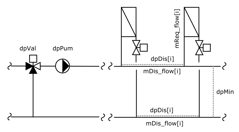
In case of a constant pressure difference at a given location, the pump head
is computed according to the schematics hereunder, under the
assumption of a two-pipe distribution system,
dpPum = dpMin + dpVal + 2 * Σi dpDis[i],
where
- dpMin is the differential pressure set point.
- dpVal is the pressure drop across the optional mixing valve. It is considered independent from the valve position, i.e., dpVal = dpVal_nominal,
-
dpDis[i] is the pressure drop in the supply pipe segment directly
upstream the ith connection,
dpDis[i] = 1 / K[i]2 * mDis_flow[i] 2,
where mDis_flow[i] = Σi to nUni mReq_flow[i] is the mass flow rate in the same pipe segment, and K[i] = (Σi to nUni mUni_flow_nominal[i]) / dpDis_nominal[i]0.5 is the corresponding flow coefficient (constant).
-
The pressure drop in the corresponding pipe segment of the return line is considered equal, hence the factor of 2 in the above equation.
The default value for
dpDis_nominalcorresponds to a configuration where the differential pressure sensor is located before the most remote connected unit, 20% of the nominal pressure drop in the distribution network occurs between the pump and the first connected unit (supply and return), the remaining pressure drop is evenly distributed over each pipe segment between the other connected units. The user can override these default values with the requirement that the nominal pressure drop of each pipe segment downstream of the differential pressure sensor must be set to zero.
Energy and mass dynamics
The energy dynamics and the time constant used in the ideal heater and cooler model are exposed as advanced parameters. They are used to represent the typical dynamics over the whole piping network, from supply to return. The mass dynamics are by default identical to the energy dynamics.
Simplifying assumptions are used otherwise, namely
- the pump is modeled in steady-state, and
- the valve and the flow splitter are modeled with fixed initial conditions. This is because the temperature of the fluid leaving the valve is used as a control input signal. If a steady-state model is used, that temperature is computed by assuming ideal mixing at the inner fluid ports of the valve. In case of zero flow rate, the temperature value results from regularizing the corresponding equation that is not well defined in that domain. That triggers non-physical temperature variations which themselves lead to control transients when the flow rate gets reestablished. Those effects turn out to be detrimental to computational performance.
Computational performance
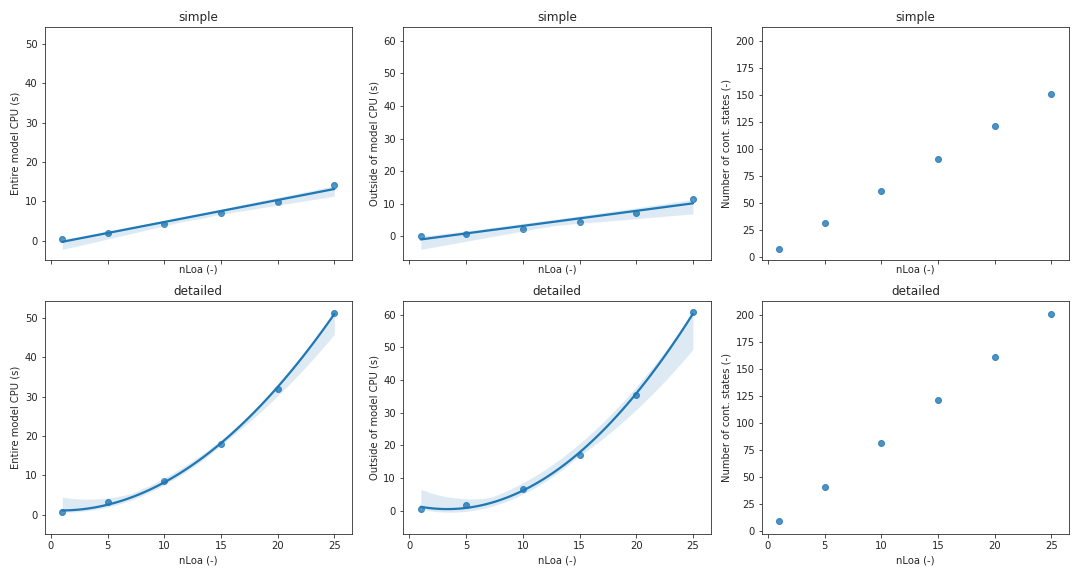
The figure below compares the computational performance of this model
(labelled simple, see model
Buildings.DHC.Loads.BaseClasses.Validation.BenchmarkFlowDistribution1)
with an explicit modeling of the distribution network and
the terminal unit actuators (labelled detailed, see model
Buildings.DHC.Loads.BaseClasses.Validation.BenchmarkFlowDistribution2).
The models are simulated with the solver CVODE from Sundials.
The impact of a varying number of connected loads, nLoa, is
assessed on
- the total time for all model evaluations,
- the total time spent between model evaluations, and
- the number of continuous state variables.
A linear, resp. quadratic, regression line and the corresponding confidence interval are
also plotted for the model labelled simple, resp. detailed.
Parameters
| Type | Name | Default | Description |
|---|---|---|---|
| Integer | nPorts_a1 | 0 | Number of terminal units return ports |
| Integer | nPorts_b1 | 0 | Number of terminal units supply ports |
| Integer | nUni | nPorts_a1 | Number of served units |
| Boolean | have_pum | false | Set to true if the system has a pump |
| Boolean | have_val | false | Set to true if the system has a mixing valve |
| Type_dis | typDis | Type_dis.HeatingWater | Type of distribution system |
| Type_ctr | typCtr | Type_ctr.ConstantHead | Type of distribution pump control |
| Modelica.Units.SI.PressureDifference | dpMin | dp_nominal/2 | Pressure difference set point for ConstantDp or at zero flow for LinearHead |
| Assumptions | |||
| Boolean | allowFlowReversal (from PartialTwoPort) | true | = false to simplify equations, assuming, but not enforcing, no flow reversal |
| Nominal condition | |||
| Modelica.Units.SI.MassFlowRate | m_flow_nominal (from PartialTwoPortInterface) | Nominal mass flow rate | |
| Real | spePum_nominal | 1 | Pump speed at nominal conditions |
| Modelica.Units.SI.PressureDifference | dp_nominal | Pressure drop at nominal conditions | |
| Modelica.Units.SI.PressureDifference | dpVal_nominal | if have_val then 0.1*dp_nominal else 0 | Mixing valve pressure drop at nominal conditions |
| Modelica.Units.SI.PressureDifference[:] | dpDis_nominal | if nUni == 1 then {1/2*(dp_nominal - dpVal_nominal - dpMin)} else 1/2.*cat(1, {(dp_nominal - dpVal_nominal - dpMin)*0.2}, fill((dp_nominal - dpVal_nominal - dpMin)*0.8/(nUni - 1), nUni - 1)) | Pressure drop between each connected unit at nominal conditions (supply line): use zero for each connection downstream the differential pressure sensor |
| Modelica.Units.SI.MassFlowRate[:] | mUni_flow_nominal | fill(m_flow_nominal/nUni, nUni) | Mass flow rate of each connected unit at nominal conditions |
| Advanced | |||
| Modelica.Units.SI.MassFlowRate | m_flow_small (from PartialTwoPortInterface) | 1E-4*abs(m_flow_nominal) | Small mass flow rate for regularization of zero flow |
| Advanced › Diagnostics | |||
| Boolean | show_T (from PartialTwoPortInterface) | false | = true, if actual temperature at port is computed |
| Dynamics › Conservation equations | |||
| Modelica.Fluid.Types.Dynamics | energyDynamics | Modelica.Fluid.Types.Dynamics.FixedInitial | Type of energy balance (except for the pump always modeled in steady state) |
| Modelica.Fluid.Types.Dynamics | massDynamics | energyDynamics | Type of mass balance (except for the pump always modeled in steady state) |
| Dynamics › Nominal condition | |||
| Modelica.Units.SI.Time | tau | 120 | Time constant of fluid temperature variation at nominal flow rate |
Connectors
| Type | Name | Default | Description |
|---|---|---|---|
| Modelica.Fluid.Interfaces.FluidPort_a | port_a (from PartialTwoPort) | Fluid connector a (positive design flow direction is from port_a to port_b) | |
| Modelica.Fluid.Interfaces.FluidPort_b | port_b (from PartialTwoPort) | Fluid connector b (positive design flow direction is from port_a to port_b) | |
| Modelica.Fluid.Interfaces.FluidPorts_a[nPorts_a1] | ports_a1 | Terminal units return ports | |
| Modelica.Fluid.Interfaces.FluidPorts_b[nPorts_b1] | ports_b1 | Terminal units supply ports | |
| Modelica.Blocks.Interfaces.RealInput[nUni] | mReq_flow | Heating or chilled water flow rate required to meet the load | |
| Modelica.Blocks.Interfaces.IntegerInput | modChaOve | Operating mode in change-over (1 for heating, 2 for cooling) | |
| Modelica.Blocks.Interfaces.RealInput | TSupSet | Supply temperature set point | |
| Modelica.Blocks.Interfaces.RealOutput | mReqTot_flow | Total heating or chilled water flow rate required to meet the loads | |
| Modelica.Blocks.Interfaces.RealOutput | QActTot_flow | Total heat flow rate transferred to the loads (>=0 for heating) | |
| Modelica.Blocks.Interfaces.RealOutput | PPum | Power drawn by pump motor |
Components
| Type | Name | Default | Description |
|---|---|---|---|
| Modelica.Units.SI.MassFlowRate | m_flow (from PartialTwoPortInterface) | port_a.m_flow | Mass flow rate from port_a to port_b (m_flow > 0 is design flow direction) |
| Modelica.Units.SI.PressureDifference | dp (from PartialTwoPortInterface) | port_a.p - port_b.p | Pressure difference between port_a and port_b |
| Medium.ThermodynamicState | sta_a (from PartialTwoPortInterface) | if allowFlowReversal then Medium.setState_phX(port_a.p, noEvent(actualStream(port_a.h_outflow)), noEvent(actualStream(port_a.Xi_outflow))) else Medium.setState_phX(port_a.p, noEvent(inStream(port_a.h_outflow)), noEvent(inStream(port_a.Xi_outflow))) | Medium properties in port_a |
| Medium.ThermodynamicState | sta_b (from PartialTwoPortInterface) | if allowFlowReversal then Medium.setState_phX(port_b.p, noEvent(actualStream(port_b.h_outflow)), noEvent(actualStream(port_b.Xi_outflow))) else Medium.setState_phX(port_b.p, noEvent(port_b.h_outflow), noEvent(port_b.Xi_outflow)) | Medium properties in port_b |
| Buildings.Controls.OBC.CDL.Reals.MultiSum | sumMasFloReq | Total required mass flow rate | |
| Buildings.Fluid.Sources.MassFlowSource_T[nUni] | sou_m_flow | Source for terminal units supplied flow rate | |
| Buildings.Fluid.Sources.Boundary_pT | sin | Sink for terminal units return flow rate | |
| Buildings.Controls.OBC.CDL.Reals.MultiSum | Q_flowSum | Total heat flow rate | |
| Modelica.Blocks.Sources.RealExpression[nUni] | mAct_flow | Actual supplied mass flow rate | |
| Modelica.Blocks.Sources.RealExpression[nUni] | QAct_flow | Actual heat flow rate transferred to each load | |
| Buildings.Fluid.Actuators.Valves.ThreeWayEqualPercentageLinear | val | Mixing valve | |
| Buildings.Fluid.Movers.BaseClasses.IdealSource | pipPre | Fictitious pipe used to prescribe pump head or flow rate | |
| Buildings.Fluid.HeatExchangers.HeaterCooler_u | heaCoo | Heat transfer from the terminal units to the distribution system | |
| Buildings.Fluid.FixedResistances.Junction | spl | Flow splitter | |
| Buildings.Fluid.Sensors.MassFlowRate | senMasFlo | Supply mass flow rate sensor | |
| Buildings.Controls.OBC.CDL.Routing.RealScalarReplicator | reaRep | Repeat input to output an array | |
| Buildings.DHC.Loads.BaseClasses.Controls.MixingValveControl | conVal | Mixing valve controller | |
| Modelica.Blocks.Sources.RealExpression | dpNetVal | Pressure drop over the distribution network (excluding mixing valve) | |
| Modelica.Blocks.Sources.RealExpression | masFloPum | Pump mass flow rate value | |
| Modelica.Blocks.Sources.RealExpression | spePum | Pump speed (fractional) | |
| Buildings.Fluid.Movers.Preconfigured.FlowControlled_m_flow | pumFlo | Distribution pump with prescribed mass flow rate | |
| Buildings.Fluid.Movers.Preconfigured.SpeedControlled_y | pumSpe | Distribution pump with prescribed speed (fractional) | |
| Fluid.Sensors.TemperatureTwoPort | senTSup | Supply temperature |
Revisions
-
August 30, 2022, by Hongxiang Fu:
Swapped the pump models for preconfigured versions and removed the pump curve recordper. This is for #3099. -
December 12, 2021, by Michael Wetter:
Added parameter assignment forpumFlo.per.V_flowandpumFlo.per.pressure. This avoids in OPTIMICA a compiler error "Could not evaluate binding expression for structural parameter 'disFloHea.pumFlo.eff.per.pressure.V_flow'". -
February 21, 2020, by Antoine Gautier:
First implementation.