
modelPartialTerminalUnit
Information
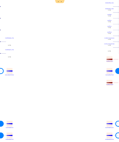
Partial model to be used for modeling an HVAC terminal unit.
The models inheriting from this class are typically used in conjunction with Buildings.DHC.Loads.BaseClasses.FlowDistribution. They must compute a so-called required mass flow rate defined as the heating or chilled water mass flow rate needed to meet the load. It can be approximated using a control loop to avoid inverting a heat exchanger model as illustrated in Buildings.DHC.Loads.BaseClasses.Examples.
The model connectivity can be modified to address various use cases:
-
On the source side (typically connected to
Buildings.DHC.Loads.BaseClasses.FlowDistribution):
-
Fluid ports for chilled water and heating water can be conditionally
instantiated by respectively setting
have_chiWatandhave_heaWatto true.
-
Fluid ports for chilled water and heating water can be conditionally
instantiated by respectively setting
-
On the load side (typically connected to a room model):
-
Fluid ports can be conditionally instantiated by setting
have_fluPorto true. -
Alternatively heat ports (for convective and radiative heat transfer)
can be conditionally instantiated by setting
have_heaPorto true. -
Real input connectors can be conditionally instantiated by setting
have_QReq_flowto true. Those connectors can be used to provide heating and cooling loads as time series, see Buildings.DHC.Loads.BaseClasses.Examples.CouplingTimeSeries for an illustration of that use case. The impact on the room air temperature of an unmet load can be assessed with Buildings.DHC.Loads.BaseClasses.SimpleRoomODE.
-
Fluid ports can be conditionally instantiated by setting
The heating or cooling nominal capacity is provided for the water based heat exchangers only. Electric heating or cooling systems are supposed to have an infinite capacity.
Connection with the flow distribution model
When connecting the model to Buildings.DHC.Loads.BaseClasses.FlowDistribution:
- The nominal pressure drop on the source side (heating or chilled water) is irrelevant as the computation of the pump head relies on a specific algorithm described in Buildings.DHC.Loads.BaseClasses.FlowDistribution.
-
The parameter
allowFlowReversalmust be set tofalse(default) in consistency with Buildings.DHC.Loads.BaseClasses.FlowDistribution. This requirement only applies to the source side. On the load side one is free to use whatever option suitable for the modeling needs. Note that typically for an air flow network connected to the outdoor air (either at the room level for modeling infiltration or at the system level for the fresh air source), the unidirectional air flow condition cannot be guaranteed. The reason is the varying pressure of the outdoor air that can lead to a negative pressure difference at the terminal unit boundaries when the fan is off.
Scaling
Scaling is implemented by means of two multiplier factors.
-
The parameter
facMulserves as a terminal unit multiplier. Each extensive quantity (mass and heat flow rate, electric power) flowing out through fluid or heat ports, or connected to an output connector is multiplied byfacMul. Each extensive quantity (mass and heat flow rate, electric power) flowing in through fluid or heat ports, or connected to an input connector is multiplied by1/facMul. This parameter allows modeling, with a single instance, multiple identical units served by the same distribution system, and serving an aggregated load (e.g., a thermal zone representing several rooms). -
The parameter
facMulZonserves as a thermal zone multiplier. Except for the variables connected to the load side, which are not affected byfacMulZon, the logic is otherwise identical to the one described forfacMul. This parameter allows modeling, with a single instance (of both the terminal unit model and the load model), multiple identical units served by the same distribution system, and serving multiple identical loads (e.g., a thermal zone representing a single room).
Note that the two multiplier factors serve different modeling purposes. As such they typically should not be used simultaneously. Both multiplier factors are of type real (as opposed to integer) to allow for instance modeling a set of terminal units based on manufacturer data, while still being able to size the full set based on a peak load. See Buildings.DHC.Loads.BaseClasses.Validation.TerminalUnitScaling for an illustration of the use case when heating and cooling loads are provided as time series.
Change-over mode
When modeling a change-over system:
-
The parameters
have_chiWatandhave_chaOvemust both be set totrueandhave_heaWatmust be set tofalse. -
The heat exchanger is sized by providing the nominal parameters for the cooling
configuration (suffix
ChiWat). The nominal mass flow rate on the source and the load side must also be provided for the heating configuration (suffixHeaWat) as it can differ from the cooling configuration. -
The computed heat flow rate must be split into its positive part that gets
connected to
QActHea_flowand its negative part that gets connected toQActCoo_flow. -
The computed required mass flow rate must be connected to
mReqChiWat_flow.
Base class parameters
All the parameters of this base class that pertain to the nominal conditions shall not be exposed in the derived class, as this would lead to an overdetermined model. For instance, the nominal mass flow rate may not be exposed but rather computed from the nominal heat flow rate, entering and leaving fluid temperature. However, those parameters are included in the base class because other components are likely to reference them. For instance the distribution system model may use the nominal mass flow rate of each terminal unit to compute the nominal mass flow rate of the circulation pump.
Parameters
| Type | Name | Default | Description |
|---|---|---|---|
| Assumptions | |||
| Boolean | allowFlowReversal | false | Set to true to allow flow reversal in building distribution system |
| Boolean | allowFlowReversalLoa | true | Set to true to allow flow reversal on the load side |
| Scaling | |||
| Real | facMul | 1 | Multiplier factor |
| Real | facMulZon | 1 | Zone multiplier factor |
| Configuration | |||
| Boolean | have_heaWat | false | Set to true if the system uses heating water |
| Boolean | have_chiWat | false | Set to true if the system uses chilled water |
| Boolean | have_chaOve | false | Set to true if the chilled water based heat exchanger operates in change-over |
| Boolean | have_eleHea | false | Set to true if the system has electric heating system |
| Boolean | have_eleCoo | false | Set to true if the system has electric cooling system |
| Boolean | have_heaPor | false | Set to true for heat ports on the load side |
| Boolean | have_fluPor | false | Set to true for fluid ports on the load side |
| Boolean | have_TSen | false | Set to true for measured temperature as an input |
| Boolean | have_QReq_flow | false | Set to true for required heat flow rate as an input |
| Boolean | have_weaBus | false | Set to true to use a weather bus |
| Boolean | have_fan | false | Set to true if fan power is computed |
| Boolean | have_pum | false | Set to true if pump power is computed |
| Nominal condition | |||
| Modelica.Units.SI.HeatFlowRate | QHea_flow_nominal | 0 | Nominal heating capacity (>=0) |
| Modelica.Units.SI.HeatFlowRate | QCoo_flow_nominal | 0 | Nominal cooling capacity (<=0) |
| Modelica.Units.SI.MassFlowRate | mHeaWat_flow_nominal | 0 | Heating water mass flow rate at nominal conditions |
| Modelica.Units.SI.MassFlowRate | mChiWat_flow_nominal | 0 | Chilled water mass flow rate at nominal conditions |
| Modelica.Units.SI.MassFlowRate | mLoaHea_flow_nominal | 0 | Load side mass flow rate at nominal conditions in heating mode |
| Modelica.Units.SI.MassFlowRate | mLoaCoo_flow_nominal | 0 | Load side mass flow rate at nominal conditions in cooling mode |
| Modelica.Units.SI.Temperature | T_aHeaWat_nominal | 273.15 + 60 | Heating water inlet temperature at nominal conditions |
| Modelica.Units.SI.Temperature | T_bHeaWat_nominal | T_aHeaWat_nominal - 22.2 | Heating water outlet temperature at nominal conditions |
| Modelica.Units.SI.Temperature | T_aChiWat_nominal | 273.15 + 7.2 | Chilled water inlet temperature at nominal conditions |
| Modelica.Units.SI.Temperature | T_bChiWat_nominal | T_aChiWat_nominal + 5.6 | Chilled water outlet temperature at nominal conditions |
| Modelica.Units.SI.Temperature | T_aLoaHea_nominal | 273.15 + 21.1 | Load side inlet temperature at nominal conditions in heating mode |
| Modelica.Units.SI.Temperature | T_aLoaCoo_nominal | 273.15 + 26.7 | Load side inlet temperature at nominal conditions in cooling mode |
| Modelica.Units.SI.MassFraction | w_aLoaCoo_nominal | 0.011 | Load side inlet humidity ratio at nominal conditions in cooling mode |
Connectors
| Type | Name | Default | Description |
|---|---|---|---|
| Modelica.Blocks.Interfaces.RealInput | TSen | Temperature (measured) | |
| Modelica.Blocks.Interfaces.RealInput | TSetHea | Heating set point | |
| Modelica.Blocks.Interfaces.RealInput | TSetCoo | Cooling set point | |
| Modelica.Blocks.Interfaces.RealInput | QReqHea_flow | Required heat flow rate to meet heating set point (>=0) | |
| Modelica.Blocks.Interfaces.RealInput | QReqCoo_flow | Required heat flow rate to meet cooling set point (<=0) | |
| Modelica.Blocks.Interfaces.RealOutput | QActHea_flow | Heating heat flow rate transferred to the load (>=0) | |
| Modelica.Blocks.Interfaces.RealOutput | QActCoo_flow | Cooling heat flow rate transferred to the load (<=0) | |
| Modelica.Blocks.Interfaces.RealOutput | PHea | Power drawn by heating system | |
| Modelica.Blocks.Interfaces.RealOutput | PCoo | Power drawn by cooling system | |
| Modelica.Blocks.Interfaces.RealOutput | PFan | Power drawn by fans motors | |
| Modelica.Blocks.Interfaces.RealOutput | PPum | Power drawn by pumps motors | |
| Modelica.Blocks.Interfaces.RealOutput | mReqHeaWat_flow | Required heating water flow rate to meet heating set point | |
| Modelica.Blocks.Interfaces.RealOutput | mReqChiWat_flow | Required chilled water flow rate to meet cooling set point | |
| Modelica.Fluid.Interfaces.FluidPort_a | port_aLoa | Fluid stream inlet port on the load side | |
| Modelica.Fluid.Interfaces.FluidPort_b | port_bLoa | Fluid stream outlet port on the load side | |
| Modelica.Thermal.HeatTransfer.Interfaces.HeatPort_b | heaPorCon | Heat port transferring convective heat to the load | |
| Modelica.Thermal.HeatTransfer.Interfaces.HeatPort_b | heaPorRad | Heat port transferring radiative heat to the load | |
| BoundaryConditions.WeatherData.Bus | weaBus | Weather data bus | |
| Modelica.Fluid.Interfaces.FluidPort_a | port_aHeaWat | Heating water inlet port | |
| Modelica.Fluid.Interfaces.FluidPort_a | port_aChiWat | Chilled water inlet port | |
| Modelica.Fluid.Interfaces.FluidPort_b | port_bHeaWat | Heating water outlet port | |
| Modelica.Fluid.Interfaces.FluidPort_b | port_bChiWat | Chilled water outlet port |
Components
Contents
| Name | Description |
|---|---|
 Medium1 Medium1 | |
 Medium2 Medium2 |
Revisions
-
December 21, 2020, by Antoine Gautier:
Refactored scaling mechanism and renamed parameters.
This is for issue 2291. -
February 21, 2020, by Antoine Gautier:
First implementation.