blockCoolingTowerLoop
Information
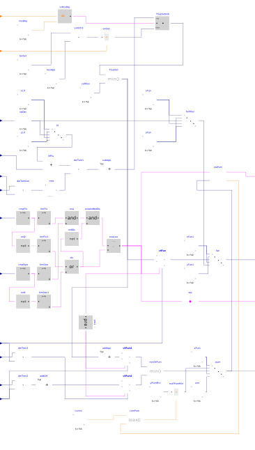
This block implements the control logic for the CT pumps and CT fans.
CT supply temperature setpoint
When Heat Rejection mode is enabled, the setpoint is equal to min(25 °C, TChiWatSupSet + dTLif - dTConWat - dTHexCoo_nominal), where TChiWatSupSet is the CHW supply temperature setpoint, dTLif is the target chiller lift (see below), dTConWat is the chiller condenser Delta-T averaged over a 5-minute moving window, and dTHexCoo_nominal is the design heat exchanger approach. The target chiller lift is reset from the minimum chiller lift to the design chiller lift when the plant required cooling capacity varies from 10 % to 100 % of the design value.
In any other mode the setpoint is equal to the minimum setpoint value of the active tank cycle minus the design heat exchanger approach.
CT pumps
The lead pump is enabled whenever the TES tank bypass valve commanded position is lower than 1 for 1 min and the CW mass flow rate through the secondary side of the cooling heat exchanger is higher than 2.5 % of design condition for 1 min. The lead pump is disabled whenever the TES tank bypass valve commanded position is equal to 1 for 1 min or the CW mass flow rate through the secondary side of the cooling heat exchanger is lower than 2.5 % of design condition for 5 min.
The lag pump is enabled whenever the pump speed command (common to all pumps) is higher than 80 % for 5 min. The lag pump is disabled whenever the pump speed command is lower than 80 % for 5 min or the lead pump is disabled.
The pump speed command is the lower of that output by two loops, each loop being enabled whenever any pump is proven on. The first loop maintains the heat exchanger leaving CW temperature on plant side at setpoint. The setpoint is equal to the CT supply temperature setpoint plus the design HX approach. The second loop maintains the Delta-T across the primary side (CT loop) of the HX at a setpoint equal to the Delta-T across the secondary side (plant side) of the HX minus 1 K. (This loop keeps the primary and secondary HX flow rates close to each other and prevents pump speed runaway when target CT supply temperature setpoint cannot be met.) The output of each loop is mapped to the minimum pump speed at 80 % to 100 % at 100 %. The minimum pump speed is provided as a parameter for each pump stage since different speeds are required for each stage to maintain minimum tower flow.
CT fans
When any of the CT pumps is commanded On, a control loop maintains the tower water supply temperature at setpoint by resetting the tower fan speed from 0 % to a maximum value varying between 70 % and 100 % when the plant required cooling capacity varies from 0 % to 50 % of the design value. Otherwise, the loop is disabled and its output set to 0 %.
Note that the fan cycling On and Off is implicitly modeled in the cooling tower component which uses a low limit of the control signal to switch to a free convection regime at zero fan power.
Parameters
| Type | Name | Default | Description |
|---|---|---|---|
| Real | mConWatHexCoo_flow_nominal | Design total CW mass flow rate through condenser barrels (all units) | |
| Integer | nCoo | Number of cooling tower cells operating at design conditions | |
| Integer | nPumConWatCoo | Number of CW pumps serving cooling towers at design conditions | |
| Real | QChiWat_flow_nominal | Design plant cooling heat flow rate (all units) | |
| Real | dTLifChi_min | Minimum chiller lift at minimum load | |
| Real | dTLifChi_nominal | Design chiller lift | |
| Real[2,2] | TTanSet | Tank temperature setpoints: 2 cycles with 2 setpoints | |
| Real | dTHexCoo_nominal | Design heat exchanger approach | |
| Real[nPumConWatCoo] | yPumConWatCoo_min | {0.2/i for i in 1:nPumConWatCoo} | Tower pump speed needed to maintain minimum tower flow (each pump stage) |
Connectors
| Type | Name | Default | Description |
|---|---|---|---|
| Buildings.Controls.OBC.CDL.Interfaces.IntegerInput | mode | Condenser loop operating mode | |
| Buildings.Controls.OBC.CDL.Interfaces.IntegerInput | idxCycTan | Index of active tank cycle | |
| Buildings.Controls.OBC.CDL.Interfaces.RealInput | TConWatCooSup | Cooling tower loop CW supply temperature | |
| Buildings.Controls.OBC.CDL.Interfaces.RealInput | mConWatHexCoo_flow | CW mass flow rate through secondary side of HX | |
| Buildings.Controls.OBC.CDL.Interfaces.RealInput | QCooReq_flow | Plant required cooling capacity (>0) | |
| Buildings.Controls.OBC.CDL.Interfaces.RealInput | TConWatConChiEnt | Chiller and HRC entering CW temperature | |
| Buildings.Controls.OBC.CDL.Interfaces.RealInput | TConWatConChiLvg | Chiller and HRC leaving CW temperature | |
| Buildings.Controls.OBC.CDL.Interfaces.RealInput | TChiWatSupSet | CHW supply temperature setpoint | |
| Buildings.Controls.OBC.CDL.Interfaces.RealInput | TConWatCooRet | Cooling tower loop CW return temperature | |
| Buildings.Controls.OBC.CDL.Interfaces.RealInput | yValBypTan | TES tank bypass valve commanded position | |
| Buildings.Controls.OBC.CDL.Interfaces.RealInput | TConWatHexCooEnt | HX entering CW temperature | |
| Buildings.Controls.OBC.CDL.Interfaces.RealInput | TConWatHexCooLvg | HX leaving CW temperature | |
| Buildings.Controls.OBC.CDL.Interfaces.BooleanOutput[nPumConWatCoo] | y1PumConWatCoo | Cooling tower pump Start command | |
| Buildings.Controls.OBC.CDL.Interfaces.RealOutput | yCoo | Cooling tower fan speed command | |
| Buildings.Controls.OBC.CDL.Interfaces.RealOutput | yPumConWatCoo | Cooling tower pump speed command | |
| Buildings.Controls.OBC.CDL.Interfaces.BooleanOutput[nCoo] | y1Coo | Cooling tower Start command |
Components
Revisions
-
February 24, 2023, by Antoine Gautier:
First implementation.