blockValveCondenserEvaporator
Information
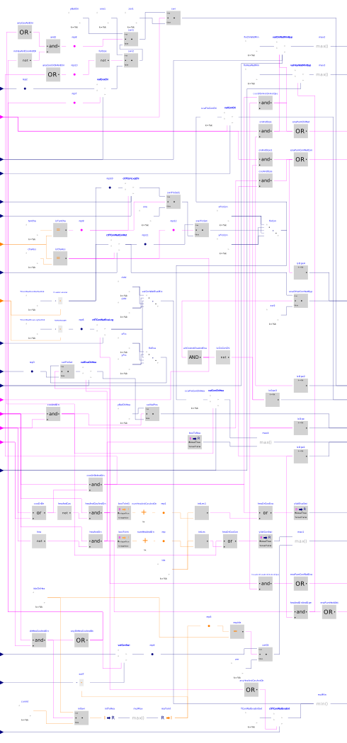
This block implements the control logic for the chiller isolation valves, the HRC isolation and switchover valves, the CHW and HW minimum flow bypass valves, the HRC evaporator CW mixing valve, and the CW chiller bypass valve. It also computes the lead pump Enable signal for the CHW, HW, CWC and CWE pump groups.
Chiller evaporator isolation valve
When a chiller is enabled, the valve position is controlled as follows.
- If no HRC is concurrently operating and connected to the CHW loop, the valve is commanded to a fully open position,
- If any HRC is concurrently operating in cascading cooling mode, but no HRC is in direct heat recovery mode, the valve is commanded to a fixed position ensuring flow balancing proportionally to design flow.
- If any HRC is concurrently operating in direct heat recovery mode, the valve is modulated with a control loop tracking an evaporator flow setpoint which is reset as described hereunder. The loop output is mapped to a valve position of 10 % (resp. 100 %) at 0 % (resp. 100 %) output signal. The loop is biased to launch from 100 %.
Otherwise, the valve is commanded to a closed position.
Chiller evaporator flow setpoint
The setpoint is computed based on the logic implemented in Buildings.DHC.Plants.Combined.Controls.BaseClasses.DirectHeatRecovery.
Chiller condenser isolation valve
When a chiller is enabled, the condenser isolation valve is modulated with a control loop tracking a condenser flow setpoint which is reset as described hereunder. The loop output is mapped to a valve position of 10 % (resp. 100 %) at 0 % (resp. 100 %) output signal. The loop is biased to launch from 100 %.
Otherwise, the valve is commanded to a closed position.
Chiller condenser flow setpoint
The condenser flow setpoint varies based on the condenser loop mode and on the tank cycle index.
- When the condenser loop mode is Charge Assist, a control loop maintains the condenser loop return temperature at a target setpoint equal to the highest temperature setpoint of the active tank cycle. The loop output is mapped to a flow setpoint of 10 % (resp. 100 %) of design flow at 0 % (resp. 100 %) output signal. The loop is biased to launch from 20 %.
- When the condenser loop mode is Tank Charge/Discharge, a control loop maintains the chiller condenser leaving temperature at target setpoint equal to the highest temperature setpoint of the active tank cycle. The loop output is mapped to a flow setpoint of 5 % (resp. 100 %) of design flow at 0 % (resp. 100 %) output signal. The loop is biased to launch from 50 %.
- When the condenser loop mode is Heat Rejection, the condenser flow setpoint is set at design value.
HRC evaporator isolation valve
When a HRC is enabled, the valve position is controlled as follows.
- If the HRC is operating in cascading cooling mode, the valve is commanded to a fixed position ensuring flow balancing proportionally to design flow.
- If the HRC is operating either in cascading heating mode or in direct heat recovery mode, the valve is modulated with a control loop tracking an evaporator flow setpoint which is reset as described hereunder. The loop output is mapped to a valve position of 10 % (resp. 100 %) at 0 % (resp. 100 %) output signal. The loop is biased to launch from 100 %.
Otherwise, the valve is commanded to a closed position.
HRC evaporator flow setpoint
In direct heat recovery mode, the setpoint is reset based on the logic implemented in Buildings.DHC.Plants.Combined.Controls.BaseClasses.DirectHeatRecovery.
In cascading heating mode, the setpoint is reset with a control loop that maintains the evaporator leaving temperature at target setpoint equal to the lowest temperature setpoint of the active tank cycle. The loop output is mapped as follows. From 0 % to 50 %, the HRC evaporator CW mixing valve commanded position is reset from 0 % (full bypass flow) to 100 % (no bypass flow). From 50 % to 100 %, the evaporator flow setpoint is reset from minimum to design value. The loop is biased to launch from 75 %. When disabled, the loop output is set to 75 % to ensure that the HRC evaporator CW mixing valve is fully open (no bypass flow).
HRC condenser isolation valve
When a HRC is enabled, the valve position is controlled as follows.
- If the HRC condenser is indexed to the HW loop (cascading heating or direct heat recovery mode), the valve is commanded to a fully open position.
- If the HRC condenser is indexed to the CW loop (cascading cooling mode), the valve is modulated with a control loop tracking a condenser flow setpoint which is reset based on the same logic as for the chiller condenser flow setpoint (see above). The loop output is mapped to a valve position of 10 % (resp. 100 %) at 0 % (resp. 100 %) output signal. The loop is biased to launch from 100 %.
Otherwise, the valve is commanded to a closed position.
HRC condenser and evaporator switchover valve
Each valve is commanded to a fully open or fully closed position depending on the valve index and the current operating mode of the HRC (cascading cooling, cascading heating or direct heat recovery). In addition, the condenser switchover valve indexed to the HRC which is nearest to the interconnection with the condenser loop (highest index) and which is operating in direct heat recovery mode is modulated with a control loop tracking the condenser entering temperature. The condenser entering temperature setpoint is reset based on the logic implemented in Buildings.DHC.Plants.Combined.Controls.BaseClasses.DirectHeatRecovery. This allows false loading the HRC that is controlled to meet the HW supply temperature setpoint in direct heat recovery mode, and thus meeting the CHW supply temperature setpoint simultaneously.
HRC evaporator CW mixing valve
The valve is modulated based on two control loops: the HRC evaporator leaving temperature control loop (see the section HRC evaporator flow setpoint) and another control loop that maintains the HRC evaporator entering water temperature below the highest tank temperature setpoint. This latter control loop is enabled when any HRC is operating in cascading heating mode. When the loop is enabled, the loop output is mapped to a valve position of 100 % (resp. 0 %) at 0 % (resp. 100 %) output signal. When the loop is disabled, the loop output is set to 100 % (no bypass flow). The valve control signal is the minimum (maximum bypass flow) of the resulting signals of those two control loops.
CHW and HW minimum flow bypass valve
Each chiller and HRC has its own CHW (resp. HW) minimum flow control loop. The loop is enabled whenever the unit's evaporator (resp. condenser) is indexed to the CHW (resp. HW) loop and its evaporator (resp. condenser) isolation valve is commanded open (with a threshold of 10 %). When enabled, each loop tracks a flow setpoint equal to 1.1 times the minimum CHW (resp. HW) flow rate. When disabled, each loop output is set to 0 %. The valve control signal is the maximum (maximum bypass flow) of the resulting signals of all control loops.
CW chiller bypass valve
The valve control is enabled when the plant is enabled either in cooling or heating mode, the Charge Assist mode is active and all chiller condenser isolation valves are closed (based on their commanded position).
When the valve control is enabled the valve position is modulated by the same control loop used to maintain the condenser loop return temperature at a target setpoint equal to the highest temperature setpoint of the active tank cycle (see the section "Chiller condenser flow setpoint").
Otherwise, the valve is commanded to a closed position.
CHW, HW, CWC, CWE lead pump
The lead pump of each loop is enabled whenever any chiller or HRC is indexed to the loop and the corresponding evaporator or condenser isolation valve is commanded open (with a threshold of 10 %). In addition, the CWC lead pump may also be enabled if the CW chiller bypass valve is commanded open.
Parameters
| Type | Name | Default | Description |
|---|---|---|---|
| Real | yBalEvaChi | if dpEvaChiHea_nominal + dpValEvaChiHea_nominal - dpEvaChi_nominal <= 0 then 1 else (dpValEvaChi_nominal/(dpEvaChiHea_nominal + dpValEvaChiHea_nominal - dpEvaChi_nominal))^0.5 | Chiller evaporator isolation valve opening for flow balancing with HRC |
| Real | yBalEvaChiHea | if dpEvaChi_nominal + dpValEvaChi_nominal - dpEvaChiHea_nominal <= 0 then 1 else (dpValEvaChiHea_nominal/(dpEvaChi_nominal + dpValEvaChi_nominal - dpEvaChiHea_nominal))^0.5 | HRC evaporator isolation valve opening for flow balancing with chiller |
| CHW loop and cooling-only chillers | |||
| Integer | nChi | Number of units operating at design conditions | |
| Real | mChiWatChi_flow_nominal | Chiller CHW design mass flow rate (value will be used for each unit) | |
| Real | mChiWatChi_flow_min | Chiller CHW minimum mass flow rate (value will be used for each unit) | |
| Real | mConWatChi_flow_nominal | Chiller CW design mass flow rate (value will be used for each unit) | |
| Real | dpEvaChi_nominal | Chiller evaporator design pressure drop (value will be used for each unit) | |
| Real | dpValEvaChi_nominal | Chiller evaporator isolation valve design pressure drop (value will be used for each unit) | |
| HW loop and heat recovery chillers | |||
| Integer | nChiHea | Number of units operating at design conditions | |
| Real | mChiWatChiHea_flow_nominal | HRC CHW design mass flow rate (value will be used for each unit) | |
| Real | mChiWatChiHea_flow_min | HRC CHW minimum mass flow rate (value will be used for each unit) | |
| Real | mConWatChiHea_flow_nominal | HRC CW design mass flow rate (value will be used for each unit) | |
| Real | mHeaWatChiHea_flow_min | Chiller HW minimum mass flow rate (value will be used for each unit) | |
| Real | dpEvaChiHea_nominal | Design chiller evaporator pressure drop (value will be used for each unit) | |
| Real | dpValEvaChiHea_nominal | HRC evaporator isolation valve design pressure drop (value will be used for each unit) | |
| CW loop, TES tank and heat pumps | |||
| Real[2,2] | TTanSet | Tank temperature setpoints: 2 cycles with 2 setpoints | |
| Control parameters | |||
| Real | k | 0.01 | Gain of controller |
| Real | Ti | 60 | Time constant of integrator block |
| Real | yMin | 0.1 | Lower limit of valve opening when control loop enabled |
| Real | y_reset | 1 | Value to which the controller output is reset if the boolean trigger has a rising edge |
| Real | y_neutral | 0 | Value to which the controller output is reset when the controller is disabled |
Connectors
| Type | Name | Default | Description |
|---|---|---|---|
| Buildings.Controls.OBC.CDL.Interfaces.IntegerInput | idxCycTan | Index of active tank cycle | |
| Buildings.Controls.OBC.CDL.Interfaces.IntegerInput | mode | Condenser loop operating mode | |
| Buildings.Controls.OBC.CDL.Interfaces.BooleanInput[nChi] | u1Chi | Cooling-only chiller On/Off command | |
| Buildings.Controls.OBC.CDL.Interfaces.BooleanInput[nChiHea] | u1ChiHea | HRC On/Off command | |
| Buildings.Controls.OBC.CDL.Interfaces.BooleanInput[nChiHea] | u1CooChiHea | HRC cooling mode switchover command: true for cooling, false for heating | |
| Buildings.Controls.OBC.CDL.Interfaces.BooleanInput[nChiHea] | u1HeaCooChiHea | HRC direct heat recovery switchover command: true for direct HR, false for cascading | |
| Buildings.Controls.OBC.CDL.Interfaces.RealInput[nChiHea] | TEvaLvgChiHea | HRC evaporator barrel leaving temperature | |
| Buildings.Controls.OBC.CDL.Interfaces.RealInput | mEvaChiSet_flow | Chiller evaporator flow setpoint | |
| Buildings.Controls.OBC.CDL.Interfaces.RealInput | mEvaChiHeaSet_flow | HRC evaporator flow setpoint | |
| Buildings.Controls.OBC.CDL.Interfaces.RealInput[nChi] | mEvaChi_flow | Chiller evaporator mass flow rate | |
| Buildings.Controls.OBC.CDL.Interfaces.RealInput[nChi] | mConChi_flow | Chiller condenser mass flow rate | |
| Buildings.Controls.OBC.CDL.Interfaces.RealInput[nChiHea] | mEvaChiHea_flow | HRC evaporator mass flow rate | |
| Buildings.Controls.OBC.CDL.Interfaces.RealInput | TConWatEvaEnt | HRC evaporator entering CW temperature | |
| Buildings.Controls.OBC.CDL.Interfaces.RealInput[nChiHea] | mConChiHea_flow | HRC condenser mass flow rate | |
| Buildings.Controls.OBC.CDL.Interfaces.RealInput | TConEntChiHeaSet | HRC condenser entering temperature setpoint | |
| Buildings.Controls.OBC.CDL.Interfaces.RealInput[nChiHea] | TConEntChiHea | HRC condenser entering temperature | |
| Buildings.Controls.OBC.CDL.Interfaces.RealInput[nChiHea] | TConLvgChiHea | HRC condenser barrel leaving temperature | |
| Buildings.Controls.OBC.CDL.Interfaces.RealInput[nChi] | TConLvgChi | Chiller condenser barrel leaving temperature | |
| Buildings.Controls.OBC.CDL.Interfaces.RealInput | TConWatConRet | CWC return temperature | |
| Buildings.Controls.OBC.CDL.Interfaces.BooleanOutput | y1PumChiWat | Enable signal for lead CHW pump | |
| Buildings.Controls.OBC.CDL.Interfaces.BooleanOutput | y1PumHeaWat | Enable signal for lead HW pump | |
| Buildings.Controls.OBC.CDL.Interfaces.BooleanOutput | y1PumConWatCon | Enable signal for lead CW pump serving evaporator loop | |
| Buildings.Controls.OBC.CDL.Interfaces.BooleanOutput | y1PumConWatEva | Enable signal for lead CW pump serving evaporator loop | |
| Buildings.Controls.OBC.CDL.Interfaces.RealOutput[nChi] | yValEvaChi | Cooling-only chiller evaporator isolation valve commanded position | |
| Buildings.Controls.OBC.CDL.Interfaces.RealOutput[nChi] | yValConChi | Cooling-only chiller condenser isolation valve commanded position | |
| Buildings.Controls.OBC.CDL.Interfaces.RealOutput[nChiHea] | yValEvaChiHea | HRC evaporator isolation valve commanded position | |
| Buildings.Controls.OBC.CDL.Interfaces.RealOutput[nChiHea] | yValConChiHea | HRC condenser isolation valve commanded position | |
| Buildings.Controls.OBC.CDL.Interfaces.RealOutput[nChiHea] | yValEvaSwiChiHea | HRC evaporator switchover valve commanded position | |
| Buildings.Controls.OBC.CDL.Interfaces.RealOutput[nChiHea] | yValConSwiChiHea | HRC condenser switchover valve commanded position | |
| Buildings.Controls.OBC.CDL.Interfaces.RealOutput | yValConWatEvaMix | HRC evaporator CW mixing valve commanded position | |
| Buildings.Controls.OBC.CDL.Interfaces.RealOutput | yValChiWatMinByp | CHW minimum flow bypass valve control signal | |
| Buildings.Controls.OBC.CDL.Interfaces.RealOutput | yValHeaWatMinByp | HW minimum flow bypass valve control signal | |
| Buildings.Controls.OBC.CDL.Interfaces.RealOutput | yValConWatByp | CW chiller bypass valve control signal | |
| Buildings.Controls.OBC.CDL.Interfaces.BooleanInput | u1CooOrHea | Plant Enable signal: either cooling or heating is enabled |
Components
| Type | Name | Default | Description |
|---|---|---|---|
| Buildings.Controls.OBC.Utilities.PIDWithEnable[nChi] | valEvaChi | Chiller evaporator isolation valve control when HRC in direct HR | |
| Buildings.Controls.OBC.Utilities.PIDWithEnable[nChi] | valConChi | Chiller condenser isolation valve control | |
| Buildings.Controls.OBC.Utilities.PIDWithEnable[nChiHea] | valEvaChiHea | HRC evaporator isolation valve control | |
| Buildings.Controls.OBC.Utilities.PIDWithEnable[nChiHea] | valConChiHea | HRC condenser isolation valve control | |
| Buildings.Controls.OBC.CDL.Conversions.BooleanToReal[nChiHea] | yValConSwi | HRC condenser switchover valve commanded position | |
| Buildings.Controls.OBC.CDL.Logical.Not[nChiHea] | hea | Return true if heating | |
| Buildings.Controls.OBC.CDL.Conversions.BooleanToInteger[nChiHea] | booToInt | Convert | |
| Buildings.Controls.OBC.CDL.Integers.MultiSum | numHeaAndOn | Number of HRC connected to HW loop and On | |
| Buildings.Controls.OBC.CDL.Integers.Less[nChiHea] | intLes | Return true if switchover valve to be open for heating operation | |
| Buildings.Controls.OBC.CDL.Routing.IntegerScalarReplicator | rep | Replicate | |
| Buildings.Controls.OBC.CDL.Logical.Or[nChiHea] | heaOrCooCon | Return true if switchover valve to be open for heating or cooling operation | |
| Buildings.Controls.OBC.CDL.Logical.And[nChiHea] | heaAndOn | Return true if heating AND On | |
| Buildings.Controls.OBC.CDL.Integers.Sources.Constant[nChiHea] | idx | HRC index | |
| Buildings.Controls.OBC.CDL.Logical.Or[nChiHea] | cooOrDir | Return true if cooling OR direct HR | |
| Buildings.Controls.OBC.CDL.Conversions.BooleanToReal[nChiHea] | yValEvaSwi | HRC evaporator switchover valve commanded position | |
| Buildings.Controls.OBC.CDL.Logical.Not[nChiHea] | heaAndCas | Return true if cascading heating | |
| Buildings.Controls.OBC.CDL.Conversions.BooleanToInteger[nChiHea] | booToInt1 | Convert | |
| Buildings.Controls.OBC.CDL.Integers.MultiSum | numHeaAndCasAndOn | Number of HRC in cascading heating AND On | |
| Buildings.Controls.OBC.CDL.Routing.IntegerScalarReplicator | rep1 | Replicate | |
| Buildings.Controls.OBC.CDL.Integers.Less[nChiHea] | intLes1 | Return true if switchover valve to be open for heating operation | |
| Buildings.Controls.OBC.CDL.Logical.Or[nChiHea] | heaOrCooEva | Return true if switchover valve to be open for heating or cooling operation | |
| Buildings.Controls.OBC.CDL.Logical.And[nChiHea] | cooOrDirAndOn | Return true if (cooling OR direct HR) AND On | |
| Buildings.Controls.OBC.CDL.Logical.And[nChiHea] | heaAndCasAndOn | Return true if cascading heating AND On | |
| Buildings.Controls.OBC.CDL.Reals.GreaterThreshold[nChiHea] | isOpe | Check if valve open | |
| Buildings.Controls.OBC.CDL.Reals.GreaterThreshold[nChiHea] | isOpe1 | Check if valve open | |
| Buildings.Controls.OBC.CDL.Reals.GreaterThreshold[nChi] | isOpe2 | Check if valve open | |
| Buildings.Controls.OBC.CDL.Reals.GreaterThreshold[nChi] | isOpe3 | Check if valve open | |
| Buildings.Controls.OBC.CDL.Logical.And[nChiHea] | cooOrDirAndOnAndOpe | Return true if HRC (cooling OR direct HR) AND On AND isolation valve open | |
| Buildings.Controls.OBC.CDL.Logical.And[nChi] | onAndOpe | Return true if On AND isolation valve open | |
| Buildings.Controls.OBC.CDL.Logical.And[nChi] | onAndOpe1 | Return true if On AND isolation valve open | |
| Buildings.Controls.OBC.CDL.Logical.MultiOr | enaPumChiWat | Enable signal for lead CHW pump | |
| Buildings.Controls.OBC.CDL.Logical.MultiOr | enaPumConWatCon | Enable signal for lead CW pump serving condenser loop | |
| Buildings.Controls.OBC.CDL.Logical.And[nChiHea] | cooAndOpe | Return true if cooling (necessarily cascading) AND isolation valve open | |
| Buildings.Controls.OBC.CDL.Logical.MultiOr | enaPumHeaWat | Enable signal for lead HW pump | |
| Buildings.Controls.OBC.CDL.Logical.MultiOr | enaPumConWatEva | Enable signal for lead CW pump serving evaporator loop | |
| Buildings.Controls.OBC.CDL.Logical.And[nChiHea] | heaAndOnAndOpe | Return true if heating AND On AND isolation valve open | |
| Buildings.Controls.OBC.CDL.Logical.And[nChiHea] | heaAndCasAndOnAndOpe | Return true if cascading heating AND On AND isolation valve open | |
| Buildings.Controls.OBC.CDL.Routing.RealScalarReplicator | rep2 | Replicate | |
| Buildings.Controls.OBC.CDL.Routing.RealScalarReplicator | rep3 | Replicate | |
| Buildings.Controls.OBC.CDL.Logical.And[nChiHea] | dirHeaCooAndOn | Return true if direct HR AND On | |
| Buildings.Controls.OBC.CDL.Logical.MultiOr | anyDirHeaCooAndOn | Return true if any HRC in direct HR AND On | |
| Buildings.Controls.OBC.Utilities.PIDWithEnable | valConSwi | Condenser switchover valve control | |
| Buildings.Controls.OBC.CDL.Routing.RealScalarReplicator | rep4 | Replicate | |
| Buildings.Controls.OBC.CDL.Integers.Equal[nChiHea] | equIdx | Return true if index equals highest index of HRC in direct HR | |
| Buildings.Controls.OBC.CDL.Integers.Sources.Constant[nChiHea] | idxChiHea | HRC index | |
| Buildings.Controls.OBC.CDL.Reals.Switch[nChiHea] | selCtl | Select control signal | |
| Buildings.Controls.OBC.CDL.Reals.Sources.Constant[nChiHea] | zer | Constant | |
| Buildings.Controls.OBC.CDL.Reals.Max[nChiHea] | max1 | Take into account entering CW temperature control in direct HR mode | |
| Buildings.Controls.OBC.CDL.Routing.RealExtractor | extT | Extract value at given index | |
| Buildings.Controls.OBC.CDL.Routing.IntegerScalarReplicator | rep5 | Replicate | |
| Buildings.Controls.OBC.Utilities.PIDWithEnable[nChiHea] | ctlTConWatEvaLvg | HRC evaporator leaving temperature control | |
| Buildings.Controls.OBC.CDL.Routing.RealExtractor | TConWatEvaLvgSet | Extract value at given index | |
| Buildings.Controls.OBC.CDL.Reals.Sources.Constant[2] | TConWatEvaLvgSetCst | HRC evaporator leaving CW temperature setpoint | |
| Buildings.Controls.OBC.CDL.Routing.RealScalarReplicator | rep6 | Replicate | |
| Buildings.Controls.OBC.CDL.Reals.Line[nChiHea] | valConWatEvaMix | Mixing valve opening reset: 1 means no bypass flow | |
| Buildings.Controls.OBC.CDL.Reals.Sources.Constant[nChiHea,2] | xVal | x-value for mixing valve opening reset | |
| Buildings.Controls.OBC.CDL.Reals.Sources.Constant[nChiHea,2] | yVal | y-value for mixing valve opening reset: 1 means no bypass flow | |
| Buildings.Controls.OBC.CDL.Reals.Line[nChiHea] | floEva | HRC evaporator flow reset when On AND cascading heating | |
| Buildings.Controls.OBC.CDL.Reals.Sources.Constant[nChiHea,2] | xFlo | x-value for evaporator flow reset | |
| Buildings.Controls.OBC.CDL.Reals.Sources.Constant[nChiHea,2] | yFlo | y-value for evaporator flow reset | |
| Buildings.Controls.OBC.CDL.Reals.Switch[nChiHea] | selFloSet | Select HRC evaporator flow setpoint based on operating mode | |
| Buildings.Controls.OBC.Utilities.PIDWithEnable | ctlTConWatEvaEnt | HRC evaporator entering temperature control: 1 means no bypass flow | |
| Buildings.Controls.OBC.CDL.Logical.MultiOr | anyHeaAndCasAndOn | Return true if ANY HRC cascading heating AND On | |
| Buildings.Controls.OBC.CDL.Reals.Sources.Constant | TConWatEvaEntSet | HRC evaporator entering CW temperature setpoint | |
| Buildings.Controls.OBC.CDL.Reals.MultiMin | mulMin | Combine outputs from evaporator entering and leaving temperature control | |
| Buildings.Controls.OBC.CDL.Reals.Sources.Constant[2] | TConWatConRetSetCst | CW condenser loop return temperature setpoint | |
| Buildings.Controls.OBC.CDL.Routing.RealExtractor | TConWatConRetSet | Extract value at given index | |
| Buildings.Controls.OBC.Utilities.PIDWithEnable | ctlTConWatConRet | Condenser loop CW return temperature control | |
| Buildings.Controls.OBC.CDL.Integers.Equal | isChaAss | Check if charge assist mode is active | |
| Buildings.Controls.OBC.CDL.Integers.Sources.Constant | chaAss | Charge assist mode index | |
| Buildings.Controls.OBC.CDL.Reals.Line[nChi + nChiHea] | floCon | Condenser flow reset (normalized output) | |
| Buildings.Controls.OBC.CDL.Reals.Sources.Constant[nChi + nChiHea,2] | xFloCon | x-value for flow reset | |
| Buildings.Controls.OBC.CDL.Reals.Sources.Constant[nChi + nChiHea,2] | yFloCon | y-value for condenser flow reset | |
| Buildings.Controls.OBC.CDL.Reals.MultiplyByParameter[nChi] | scaFloConChi | Scale flow reset signal | |
| Buildings.Controls.OBC.CDL.Reals.MultiplyByParameter[nChiHea] | scaFloConChiHea | Scale flow reset signal | |
| Buildings.Controls.OBC.Utilities.PIDWithEnable[nChi + nChiHea] | ctlTConLvgChi | Condenser leaving temperature control | |
| Buildings.Controls.OBC.CDL.Integers.Sources.Constant | tanCha | Tank charge/discharge mode index | |
| Buildings.Controls.OBC.CDL.Integers.Equal | isTanCha | Check if tank charge/discharge mode is active | |
| Buildings.Controls.OBC.CDL.Routing.BooleanScalarReplicator | rep9 | Replicate | |
| Buildings.Controls.OBC.CDL.Routing.RealScalarReplicator | rep10 | Replicate | |
| Buildings.Controls.OBC.CDL.Routing.RealScalarReplicator | rep11 | Replicate | |
| Buildings.Controls.OBC.CDL.Reals.Sources.Constant[nChi + nChiHea] | one | Constant | |
| Buildings.Controls.OBC.CDL.Reals.Switch[nChi + nChiHea] | swiFloSet | Switch condenser flow setpoint based on condenser loop operating mode | |
| Buildings.Controls.OBC.CDL.Routing.BooleanScalarReplicator | rep12 | Replicate | |
| Buildings.Controls.OBC.CDL.Reals.Switch[nChi + nChiHea] | swiFloSet1 | Switch condenser flow setpoint based on condenser loop operating mode | |
| Buildings.Controls.OBC.Utilities.PIDWithEnable[nChi + nChiHea] | valChiWatMinByp | CHW minimum flow bypass valve control | |
| Buildings.Controls.OBC.Utilities.PIDWithEnable[nChiHea] | valHeaWatMinByp | HW minimum flow bypass valve control | |
| Buildings.Controls.OBC.CDL.Reals.Sources.Constant[nChi + nChiHea] | floChiWatMin | Minimum flow setpoint | |
| Buildings.Controls.OBC.CDL.Reals.Sources.Constant[nChiHea] | floHeaWatMin | Minimum flow setpoint | |
| Buildings.Controls.OBC.CDL.Reals.MultiMax | max2 | Maximum control signal | |
| Buildings.Controls.OBC.CDL.Reals.MultiMax | max3 | Maximum control signal | |
| Buildings.Controls.OBC.CDL.Routing.BooleanScalarReplicator | rep7 | Replicate | |
| Buildings.Controls.OBC.CDL.Reals.Switch[nChi] | swi | Condition to enable evaporator flow control loop | |
| Buildings.Controls.OBC.CDL.Reals.Sources.Constant[nChi] | zer1 | Constant | |
| Buildings.Controls.OBC.CDL.Logical.Not | noHeaAndCooAndOn | Return true if NO HRC in direct HR AND On | |
| Buildings.Controls.OBC.CDL.Logical.MultiOr | anyCooAndOn | Return true if ANY HRC in cascading cooling AND On | |
| Buildings.Controls.OBC.CDL.Logical.And | and2 | Condition to switch to fixed valve opening (balancing) | |
| Buildings.Controls.OBC.CDL.Routing.BooleanScalarReplicator | rep8 | Replicate | |
| Buildings.Controls.OBC.CDL.Reals.Switch[nChi] | swi1 | Condition to enable evaporator flow control loop | |
| Buildings.Controls.OBC.CDL.Reals.Sources.Constant[nChi] | yBalChi | Constant | |
| Buildings.Controls.OBC.CDL.Logical.Not[nChi] | fulOpe | Condition to switch to fixed full opening | |
| Buildings.Controls.OBC.CDL.Reals.Switch[nChi] | swi2 | Condition to enable evaporator flow control loop | |
| Buildings.Controls.OBC.CDL.Reals.Sources.Constant[nChi] | one1 | Constant | |
| Buildings.Controls.OBC.CDL.Logical.And[nChiHea] | cooAndOn | Return true if HRC in cascading cooling AND On | |
| Buildings.Controls.OBC.CDL.Reals.Switch[nChiHea] | selValPos | Select HRC evaporator isolation valve command signal | |
| Buildings.Controls.OBC.CDL.Reals.Sources.Constant[nChiHea] | yBalChiHea | Constant | |
| Buildings.Controls.OBC.CDL.Logical.MultiOr | anyCooOrDirAndOn | Return true if any HRC in (cooling OR direct HR) AND On | |
| Buildings.Controls.OBC.CDL.Routing.BooleanScalarReplicator | rep13 | Replicate | |
| Buildings.Controls.OBC.CDL.Conversions.BooleanToReal[nChiHea] | booToRea | Convert | |
| Buildings.Controls.OBC.CDL.Reals.Max[nChiHea] | max4 | Convert | |
| Buildings.Controls.OBC.CDL.Logical.Not[nChi] | isCloConChi | Check if valve closed | |
| Buildings.Controls.OBC.CDL.Logical.MultiAnd | allCloAndChaAndEna | Check if all valves closed AND Charge Assist mode is active | |
| Buildings.Controls.OBC.CDL.Reals.Switch | enaCtlValConWatByp | Enable CW bypass valve control | |
| Buildings.Controls.OBC.CDL.Reals.Sources.Constant | zer2 | Constant | |
| Buildings.Controls.OBC.CDL.Reals.GreaterThreshold | isOpe4 | Check if valve open | |
| Buildings.Controls.OBC.CDL.Integers.Switch[nChiHea] | intSwi | Switch | |
| Buildings.Controls.OBC.CDL.Integers.Sources.Constant[nChiHea] | conInt | Constant 1 | |
| Buildings.Controls.OBC.CDL.Conversions.IntegerToReal[nChiHea] | intToRea | Convert integer to real | |
| Buildings.Controls.OBC.CDL.Conversions.RealToInteger | reaToInt | Convert real to integer | |
| Buildings.Controls.OBC.CDL.Reals.MultiMax | mulMax | Maximum value of a vector input |
Revisions
-
February 24, 2023, by Antoine Gautier:
First implementation.