
modelStoragePlantDualSource
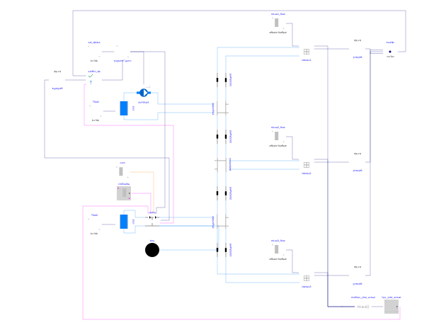
Idealised district system model with two sources and three users
Extends from Modelica.Icons.Example (Icon for runnable examples).
Information
The modelled system is described in the documentation of Buildings.DHC.Plants.Cooling.StoragePlant.
The source blocks give the system the following operation schedule during simulation:
-
At
time = 0, the system is all off. -
At
time = 200, the system is commanded to charge the tank. The chiller is available and charges the tank locally. After some time, the charging stops when the tank status signal returns that the tank is charged. -
At
time = 1800, load appears at the district network. The storage plant starts producing CHW to the system. Currently the tank is not commanded to charge or discharge, therefore it functions like a common pipe and the CHW is supplied by the chiller. -
At
time = 3500, the load increases and there is no more overflow through the tank. -
At
time = 4000, the system is commanded to have the tank take priority for CHW production. After some time, the cooling in the tank is empty and the tank stops producing. Now the chiller takes over. -
At
time = 7000, there is no longer load in the district system. The system is back to the all-off state. -
At
time = 7500, the system is once again commanded to charge the tank, but the chiller in the storage plant is not enabled. The tank is therefore charged remotely by the district. This stops once the tank is charged again.
Implementation
The chiller is implemented as an ideal temperature source using Buildings.Fluid.Sources.PropertySource_T. Its outlet temperature is always at the prescribed value.
Parameters
| Type | Name | Default | Description |
|---|---|---|---|
| Modelica.Units.SI.MassFlowRate | m_flow_nominal | 1 | Nominal mass flow rate, slightly larger than needed by one user load |
| Modelica.Units.SI.PressureDifference | dp_nominal | 300000 | Nominal pressure difference |
| Modelica.Units.SI.Temperature | T_CHWR_nominal | 12 + 273.15 | Nominal temperature of CHW return |
| Modelica.Units.SI.Temperature | T_CHWS_nominal | 7 + 273.15 | Nominal temperature of CHW supply |
| Nominal values | |||
| Modelica.Units.SI.MassFlowRate | mTan_flow_nominal | 1 | Nominal mass flow rate for CHW tank branch |
| Modelica.Units.SI.MassFlowRate | mChi_flow_nominal | 1 | Nominal mass flow rate for CHW chiller branch |
Components
| Type | Name | Default | Description |
|---|---|---|---|
| Buildings.Fluid.Sources.PropertySource_T | chi1 | Chiller 1 represented by an ideal temperature source | |
| Modelica.Blocks.Sources.Constant | TSet1 | Constant CHW leaving temperature | |
| Buildings.Fluid.Movers.Preconfigured.SpeedControlled_y | pumSup1 | CHW supply pump for chi1 | |
| Buildings.Controls.Continuous.LimPID | conPI_pumChi1 | PI controller | |
| Buildings.DHC.Plants.Cooling.Controls.SelectMin | selMin_dp | Min of pressure heads with the signal from storage plant optionally used | |
| Buildings.DHC.Plants.Cooling.StoragePlant | stoPla | Storage plant | |
| Buildings.Fluid.Sources.Boundary_pT | bou | Pressure boundary | |
| Buildings.Fluid.Sources.PropertySource_T | chi2 | Chiller represented by an ideal temperature source | |
| Modelica.Blocks.Sources.Constant | TSet2 | Constant CHW leaving temperature | |
| Modelica.Blocks.Math.Gain | gaiStoPla | Gain to normalise dp measurement | |
| Buildings.DHC.Plants.Cooling.BaseClasses.IdealUser | ideUse1 | Ideal user | |
| Buildings.DHC.Plants.Cooling.BaseClasses.IdealUser | ideUse2 | Ideal user | |
| Buildings.DHC.Plants.Cooling.BaseClasses.IdealUser | ideUse3 | Ideal user | |
| Modelica.Blocks.Sources.Constant | set_dpUse | Normalized consumer differential pressure setpoint | |
| Modelica.Blocks.Sources.TimeTable | mLoa1_flow | Cooling load of user 1 represented by flow rate | |
| Modelica.Blocks.Sources.TimeTable | mLoa2_flow | Cooling load of user 2 represented by flow rate | |
| Modelica.Blocks.Sources.TimeTable | mLoa3_flow | Cooling load of user 3 represented by flow rate | |
| Modelica.Blocks.Math.Gain | gaiUse1 | Gain to normalise dp measurement | |
| Modelica.Blocks.Math.Gain | gaiUse2 | Gain to normalise dp measurement | |
| Modelica.Blocks.Math.Gain | gaiUse3 | Gain to normalise dp measurement | |
| Buildings.DHC.Plants.Cooling.BaseClasses.ParallelJunctions | parJunPla1 | Parallel junctions for breaking algebraic loops | |
| Buildings.DHC.Plants.Cooling.BaseClasses.ParallelJunctions | parJunUse2 | Parallel junctions for breaking algebraic loops | |
| Buildings.DHC.Plants.Cooling.BaseClasses.ParallelJunctions | parJunPla2 | Parallel junctions for breaking algebraic loops | |
| Buildings.DHC.Plants.Cooling.BaseClasses.ParallelPipes | parPipS1U1 | Parallel pipes | |
| Buildings.DHC.Plants.Cooling.BaseClasses.ParallelPipes | parPipS1U2 | Parallel pipes | |
| Buildings.DHC.Plants.Cooling.BaseClasses.ParallelPipes | parPipS2U2 | Parallel pipes | |
| Buildings.DHC.Plants.Cooling.BaseClasses.ParallelPipes | parPipS2U3 | Parallel pipes | |
| Modelica.Blocks.Routing.Multiplex | muxDp | Multiplexer block for routing | |
| Buildings.Controls.OBC.CDL.Reals.MultiMax | mulMax_yVal_actual | Position of the most open user control valve | |
| Modelica.Blocks.Sources.IntegerTable | com | Command: 1 = charge tank, 2 = no command, 3 = discharge from tank | |
| Modelica.Blocks.Sources.BooleanTable | chiEnaSta | Chiller enable status, true if chiller is enabled | |
| Buildings.Controls.OBC.CDL.Reals.Hysteresis | hys_yVal_actual | Hysteresis for user control valve position |
Contents
| Name | Description |
|---|---|
 Medium Medium | Medium model for CHW |
Revisions
-
July 31, 2023, by Michael Wetter:
Revised implementation, removed unused parameter. -
January 11, 2023 by Hongxiang Fu:
First implementation. This is for #2859.