modelStoragePlant
Extends from Buildings.Fluid.Interfaces.PartialFourPort (Partial model with four ports).
Information
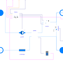
This model encompasses the components of a chilled water storage plant. It includes a flow-controlled primary pump, a stratefied storage tank, a reversible connection with the district network, and related controls to coordinate charging and discharging of the tank. The chiller is intentionally excluded in this component so that it can be otherwise chosen and configured. The tank in this plant can be charged by its local chiller or by a remote chiller on the same CHW district network.
System Concept Example
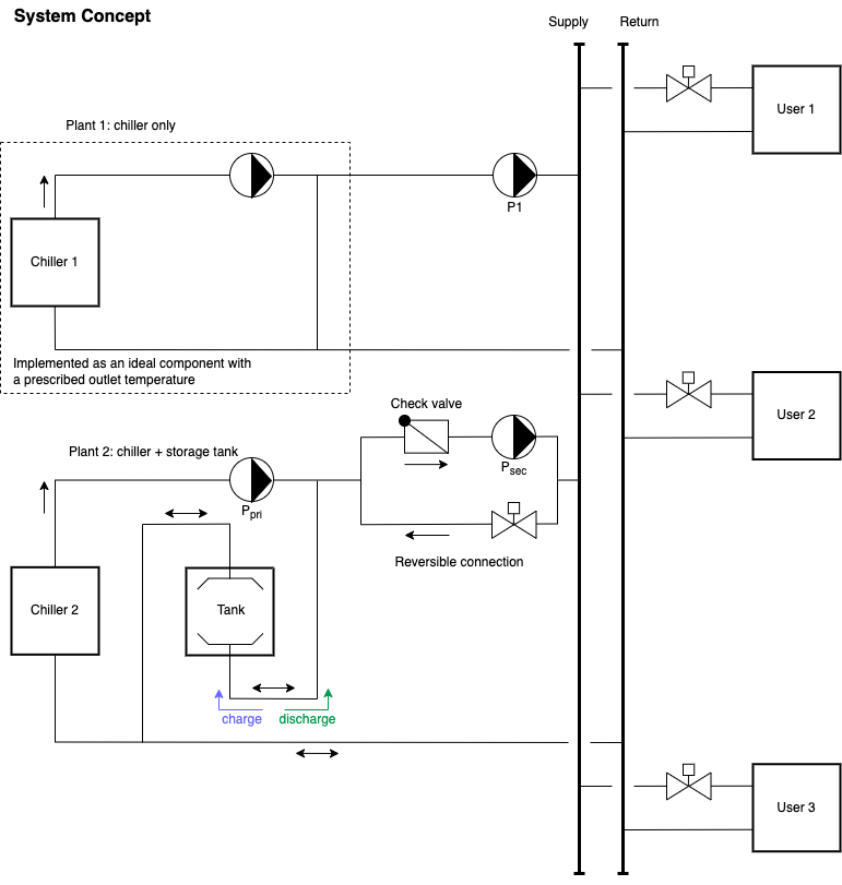
An example usage of this model within a district network is implemented in Buildings.DHC.Plants.Cooling.Examples.StoragePlantDualSource. Shown in the schematic below, it has two CHW plants and three users.
- Plant 1 only has a chiller. The supply pump, P1, is controlled to ensure that all users have enough pressure head. This represents a remote chiller plant, referenced above.
- Plant 2 has a chiller and a stratified CHW tank and is represented by this model. The storage plant has a reversible connection to the district network that can either pump water to the network from the plant using the pump Psec, or throttle water from the pressurised network to charge the tank.
Control Signals
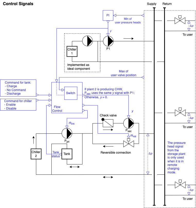
The plants are controlled as follows:
- In plant 1, for the sake of this discussion, assume the chiller is always on. The speed-controlled pump ensures that the users have enough pressure head at all times. This includes plant 2 when its tank is charged remotely by plant 1 and it acts like an energy consumer.
-
For plant 2:
- In the chiller loop, chiller 2 and its primary pump Ppri are on whenever needed (for charging the tank or producing CHW to the network). Otherwise, they are commanded off.
- The system receives one of the following three commands regarding the tank: charge, discharge, or no action. The tank controller returns status signals. It can be empty, charged, or in-between. The command to tank may be disregarded. For example, if the tank is receiving a discharge command but it is already empty, it will not discharge which would let warm return water directly into the supply side. See the Implementation section for details.
-
The reversible connection between plant 2 and the district network
modulates the flow rate needed by plant 2.
- When the storage plant produces CHW, Psec receives a speed control signal from the same PI controller as P1 in plant 1.
- When the storage plant is charged remotely, the pressure-independent valve is controlled to maintain a constant flow from the pressurised network to the storage tank.
- Otherwise, the connection cuts off flow to isolate plant 2 from the district network.
Implementation
The flow control of the storage plant is implemented as a state graph in Buildings.DHC.Plants.Cooling.Controls.FlowControl.
Parameters
| Type | Name | Default | Description |
|---|---|---|---|
| Assumptions | |||
| Boolean | allowFlowReversal1 (from PartialFourPort) | true | = false to simplify equations, assuming, but not enforcing, no flow reversal for medium 1 |
| Boolean | allowFlowReversal2 (from PartialFourPort) | true | = false to simplify equations, assuming, but not enforcing, no flow reversal for medium 2 |
| Nominal values | |||
| Modelica.Units.SI.MassFlowRate | m_flow_nominal | mTan_flow_nominal + mChi_flow_nominal | Nominal mass flow rate |
| Modelica.Units.SI.MassFlowRate | mTan_flow_nominal | Nominal mass flow rate for CHW tank branch | |
| Modelica.Units.SI.MassFlowRate | mChi_flow_nominal | Nominal mass flow rate for CHW chiller branch | |
| Modelica.Units.SI.PressureDifference | dpPum_nominal | Nominal pressure difference for secondary pump sizing | |
| Modelica.Units.SI.PressureDifference | dpVal_nominal | Nominal pressure difference for return valve sizing | |
| Modelica.Units.SI.Temperature | T_CHWS_nominal | 7 + 273.15 | Nominal temperature of CHW supply |
| Modelica.Units.SI.Temperature | T_CHWR_nominal | 12 + 273.15 | Nominal temperature of CHW return |
Connectors
| Type | Name | Default | Description |
|---|---|---|---|
| Modelica.Fluid.Interfaces.FluidPort_a | port_a1 (from PartialFourPort) | Fluid connector a1 (positive design flow direction is from port_a1 to port_b1) | |
| Modelica.Fluid.Interfaces.FluidPort_b | port_b1 (from PartialFourPort) | Fluid connector b1 (positive design flow direction is from port_a1 to port_b1) | |
| Modelica.Fluid.Interfaces.FluidPort_a | port_a2 (from PartialFourPort) | Fluid connector a2 (positive design flow direction is from port_a2 to port_b2) | |
| Modelica.Fluid.Interfaces.FluidPort_b | port_b2 (from PartialFourPort) | Fluid connector b2 (positive design flow direction is from port_a2 to port_b2) | |
| Modelica.Blocks.Interfaces.BooleanInput | chiEnaSta | Chiller enable status, true if chiller is enabled | |
| Modelica.Blocks.Interfaces.IntegerInput | com | Command: 1 = charge tank, 2 = no command, 3 = discharge from tank | |
| Modelica.Blocks.Interfaces.BooleanInput | hasLoa | Set to true if the district has a load | |
| Modelica.Blocks.Interfaces.RealInput | yPum | Normalized speed signal for the secondary pump | |
| Buildings.Controls.OBC.CDL.Interfaces.RealOutput | dp | Pressure drop accross the connection (measured) | |
| Modelica.Blocks.Interfaces.BooleanOutput | isChaRem | Is operated for remote charging |
Components
| Type | Name | Default | Description |
|---|---|---|---|
| Buildings.Fluid.Movers.Preconfigured.FlowControlled_m_flow | pumPri | Primary CHW pump | |
| Buildings.Fluid.FixedResistances.PressureDrop | chi2PreDro | Pressure drop of the chiller loop | |
| Buildings.DHC.Plants.Cooling.BaseClasses.TankBranch | tanBra | Tank branch, tank can be charged remotely | |
| Buildings.DHC.Plants.Cooling.BaseClasses.ReversibleConnection | revCon | Reversible connection | |
| Buildings.DHC.Plants.Cooling.Controls.FlowControl | floCon | Control block for storage plant flows | |
| Buildings.DHC.Plants.Cooling.Controls.TankStatus | tanSta | Tank status | |
| Buildings.Fluid.Sensors.RelativePressure | senRelPre | Relative pressure sensor |
Contents
| Name | Description |
|---|---|
 Medium Medium | Medium package |
Revisions
-
April 28, 2023 by Hongxiang Fu:
First implementation. This is for #2859.