
modelIEEE4
Extends from Modelica.Icons.Example (Icon for runnable examples).
Information
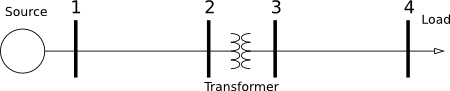
This is a partial model that is extended by all the other validation test cases. This model defined replaceable probes and transformer so they can be easily changed when implementing the different tests.
More information can be found in each model that extends this one.
Reference results
The reference results for the tests are saved as parameter of the model and compared to the simulated ones. The error between the results (herein called Xmodel) and the references (herein called Xref) are computed in both absolute and relative way. Note that Xmodel and Xref can be either voltage amplitudes or phase angles.
Errabs = Xmodel - Xref
Err% = Errabs / Xref
The variables that store the results of the comparison are listed in the table below
| Variable | Description | Unit |
|---|---|---|
err_V2[3] |
Error between simulated voltage at node 2 and reference results | [V] |
err_V3[3] |
Error between simulated voltage at node 3 and reference results | [V] |
err_V4[3] |
Error between simulated voltage at node 4 and reference results | [V] |
err_Theta2[3] |
Error between simulated phase angle at node 2 and reference phase angle | [rad], displayed as [deg] |
err_Theta3[3] |
Error between simulated phase angle at node 2 and reference phase angle | [rad], displayed as [deg] |
err_Theta4[3] |
Error between simulated phase angle at node 2 and reference phase angle | [rad], displayed as [deg] |
err_V2_percent[3] |
Relative error between simulated voltage at node 2 and reference results | [%] |
err_V3_percent[3] |
Relative error between simulated voltage at node 3 and reference results | [%] |
err_V4_percent[3] |
Relative error between simulated voltage at node 4 and reference results | [%] |
err_Theta2_percent[3] |
Relative error between simulated phase angle at node 2 and reference phase angle | [%] |
err_Theta3_percent[3] |
Relative error between simulated phase angle at node 2 and reference phase angle | [%] |
err_Theta4_percent[3] |
Relative error between simulated phase angle at node 2 and reference phase angle | [%] |
Parameters
| Type | Name | Default | Description |
|---|---|---|---|
| Modelica.Units.SI.Voltage | VLL_side1 | 12.47e3 | Voltage line to line side 1 |
| Modelica.Units.SI.Voltage | VLL_side2 | 4.16e3 | Voltage line to line side 2 |
| Modelica.Units.SI.ApparentPower | VARbase | 6000e3 | Base VA power of the transformer |
| Boolean | line1_use_Z_y | true | Choose between Zy or Zd impedance matrix for line 1 |
| Boolean | line2_use_Z_y | true | Choose between Zy or Zd impedance matrix for line 2 |
| Modelica.Units.SI.Voltage[3] | V2_ref | {7107, 7140, 7121} | Reference RMS voltage node 2 - IEEE results |
| Modelica.Units.SI.Voltage[3] | V3_ref | {2247, 2269, 2256} | Reference RMS voltage node 3 - IEEE results |
| Modelica.Units.SI.Voltage[3] | V4_ref | {1918, 2061, 1981} | Reference RMS voltage node 4 - IEEE results |
| Modelica.Units.SI.Angle[3] | Theta2_ref | {-0.3, -120.3, 119.6} | Reference voltage phase angle node 2 - IEEE results |
| Modelica.Units.SI.Angle[3] | Theta3_ref | {-3.7, -123.5, 116.4} | Reference voltage phase angle node 3 - IEEE results |
| Modelica.Units.SI.Angle[3] | Theta4_ref | {-9.1, -128.3, 110.9} | Reference voltage phase angle node 4 - IEEE results |
Components
| Type | Name | Default | Description |
|---|---|---|---|
| Modelica.Units.SI.Voltage[3] | err_V2 | node2.V - V2_ref | Error on voltage at node 2 |
| Modelica.Units.SI.Voltage[3] | err_V3 | node3.V - V3_ref | Error on voltage at node 3 |
| Modelica.Units.SI.Voltage[3] | err_V4 | node4.V - V4_ref | Error on voltage at node 4 |
| Modelica.Units.SI.Angle[3] | err_Theta2 | node2.theta - Theta2_ref | Error on voltage at node 2 |
| Modelica.Units.SI.Angle[3] | err_Theta3 | node3.theta - Theta3_ref | Error on voltage at node 3 |
| Modelica.Units.SI.Angle[3] | err_Theta4 | node4.theta - Theta4_ref | Error on voltage at node 4 |
| Real[3] | err_V2_percent | 100*{err_V2[i]/V2_ref[i] for i in 1:3} | Error in RMS voltage at node 2 -- percent |
| Real[3] | err_V3_percent | 100*{err_V3[i]/V3_ref[i] for i in 1:3} | Error in RMS voltage at node 3 -- percent |
| Real[3] | err_V4_percent | 100*{err_V4[i]/V4_ref[i] for i in 1:3} | Error in RMS voltage at node 4 -- percent |
| Real[3] | err_Theta2_percent | 100*{err_Theta2[i]/Theta2_ref[i] for i in 1:3} | Error in voltage phase angle at node 2 -- percent |
| Real[3] | err_Theta3_percent | 100*{err_Theta3[i]/Theta3_ref[i] for i in 1:3} | Error in voltage phase angle at node 3 -- percent |
| Real[3] | err_Theta4_percent | 100*{err_Theta4[i]/Theta4_ref[i] for i in 1:3} | Error in voltage phase angle at node 4 -- percent |
| Buildings.Electrical.AC.ThreePhasesUnbalanced.Sources.FixedVoltage | source | Voltage source | |
| Buildings.Electrical.AC.ThreePhasesUnbalanced.Lines.TwoPortMatrixRL | line1 | Line at primary side | |
| Buildings.Electrical.AC.ThreePhasesUnbalanced.Lines.TwoPortMatrixRL | line2 | Line at secondary side | |
| Buildings.Electrical.AC.ThreePhasesUnbalanced.Loads.Inductive | loadRL | Load | |
| Buildings.Electrical.AC.ThreePhasesUnbalanced.Sensors.BaseClasses.GeneralizedProbe | node1 | Probe at source | |
| Buildings.Electrical.AC.ThreePhasesUnbalanced.Sensors.BaseClasses.GeneralizedProbe | node2 | Probe at the primary side of the transformer | |
| Buildings.Electrical.AC.ThreePhasesUnbalanced.Sensors.BaseClasses.GeneralizedProbe | node3 | Probe at the secondary side of the transformer | |
| Buildings.Electrical.AC.ThreePhasesUnbalanced.Sensors.BaseClasses.GeneralizedProbe | node4 | Probe at the load |
Revisions
-
October 1, 2015, by Michael Wetter:
RemovedloadRL.P_nominalas the power is an input andP_nominalis disabled in this configuration. -
October 8, 2014, by Marco Bonvini:
Revised documentation. -
June 6, 2014, by Marco Bonvini:
First implementation.