
modelSystem3

Extends from Modelica.Icons.Example (Icon for runnable examples).
Information
This part of the system model adds the boiler loop with open loop control to the model that is implemented in Buildings.Examples.Tutorial.Boiler.System2.
Implementation
This model was built as follows:
-
First, we copied the model Buildings.Examples.Tutorial.Boiler.System2 and called it
Buildings.Examples.Tutorial.Boiler.System3. -
Next, we deleted the sink and source models
sinandsou, as these will be replaced by the boiler loop. -
We made various instances of Buildings.Fluid.FixedResistances.Junction to model flow splitter and mixers. We also made an instance of Buildings.Fluid.Actuators.Valves.ThreeWayEqualPercentageLinear to model the three-way valves, and an instance of Buildings.Fluid.Boilers.BoilerPolynomial to model the boiler, and we made an instance of Modelica.Thermal.HeatTransfer.Sources.FixedTemperature to model the heat loss of the boiler to the ambient.
Note that we also made an instance of Buildings.Fluid.Sources.Boundary_pT, which we called
preSou. This is required to set a pressure reference in the water loop, which is a closed system. For medium models that expand with increasing temperature, this is also required to accumulate, and to feed back into the system, the difference in mass due to the thermal expansion of water. -
Next, we parameterized the medium of all these components by setting it to
MediumW.Since the nominal mass flow rate for the boiler loop is required by several models, we introduced the following system-level parameters, where
TBoiRet_minwill be used to avoid condensation in the boiler:parameter Modelica.Units.SI.Temperature TBoiSup_nominal = 273.15+80 "Boiler nominal supply water temperature"; parameter Modelica.Units.SI.Temperature TBoiRet_min = 273.15+60 "Boiler minimum return water temperature"; parameter Modelica.Units.SI.MassFlowRate mBoi_flow_nominal= Q_flow_nominal/4200/(TBoiSup_nominal-TBoiRet_min) "Boiler nominal mass flow rate";
Next, we set the parameters of the individual component models.
-
We lumped the pressure drop of the boiler loop into the boiler model and hence set
Buildings.Fluid.Boilers.BoilerPolynomial boi( redeclare package Medium = MediumW, energyDynamics=Modelica.Fluid.Types.Dynamics.FixedInitial, m_flow_nominal=mBoi_flow_nominal, dp_nominal=2000, Q_flow_nominal=Q_flow_nominal, fue=Buildings.Fluid.Data.Fuels.HeatingOilLowerHeatingValue()) "Boiler"; -
For the three-way valve in the radiator loop, we used the default pressure drop of 6000 Pa. For its mass flow rate, we introduced the parameter
  parameter Modelica.Units.SI.MassFlowRate mRadVal_flow_nominal=
    Q_flow_nominal/4200/(TBoiSup_nominal-TRadRet_nominal)
    "Radiator nominal mass flow rate";
This allowed us to configure the valve as
  Buildings.Fluid.Actuators.Valves.ThreeWayEqualPercentageLinear valRad(
    redeclare package Medium = MediumW,
    m_flow_nominal=mRadVal_flow_nominal,
    l={0.01,0.01},
    dpValve_nominal=6000) "Three-way valve for radiator loop"
where
l={0.01,0.01}is a valve leakage of 1% anddpValve_nominal=6000is the pressure drop of the valve if it is fully open and if the mass flow rate is equal tom_flow_nominal. It is recommended to set the valve leakage to a non-zero value to avoid numerical problems. A non-zero value also represent a more realistic situation, as most valves have some leakage. -
For the bypass between the valve and the radiator, we note that the mass flow rate is equal to
mRad_flow_nominal - mRadVal_flow_nominal. This is a fixed bypass that is used to allow the valve to work across its full range. We decided to lump the pressure drop of this bypass, and the pressure drop of the radiator loop, into the instancemix. Hence, its parameters areBuildings.Fluid.FixedResistances.Junction mix( redeclare package Medium =MediumW, energyDynamics=Modelica.Fluid.Types.Dynamics.FixedInitial, m_flow_nominal={mRadVal_flow_nominal, -mRad_flow_nominal, mRad_flow_nominal-mRadVal_flow_nominal}, dp_nominal={100,-8000,6750}) "Mixer between valve and radiators";Note the negative values, which are used for the ports where the medium is outflowing at nominal conditions. See also the documentation of the model Buildings.Fluid.FixedResistances.Junction.
We also set the pressure drop of port 3 of
mixto the same value as the pressure drop of the valve in order to balance the flows. In practice, this can be done by using a balance valve, whose pressure drop we lumped into the componentmix. -
Next, we set the pressure drops and flow rates of all flow splitters and mixers. For the flow splitters and mixers that are connected to another flow splitter or mixer which already computes the pressure drop of the connecting flow leg, we set the nominal pressure drop to zero. This will remove the equation for the pressure drop calculation. However, we chose to still use the mixer and splitters to make sure that we properly defined the mixing points in the system.
-
Next, we connected all fluid ports, and we set open-loop control signals for the valves, pumps and boilers. This is implemented using the block Buildings.Controls.OBC.CDL.Reals.Sources.Constant. Using open-loop signals allows testing the model prior to adding the complexity of closed loop control. To avoid that the boiler overheats, we set its control input to
0.5. Otherwise, the boiler temperature would raise quickly when the radiator pump is off, and the simulation would stop with an error message that says that its medium temperature is outside the allowed range.
This completes the initial version of the model. When simulating the model for 2 days, or 172800 seconds, the response shown below should be seen.
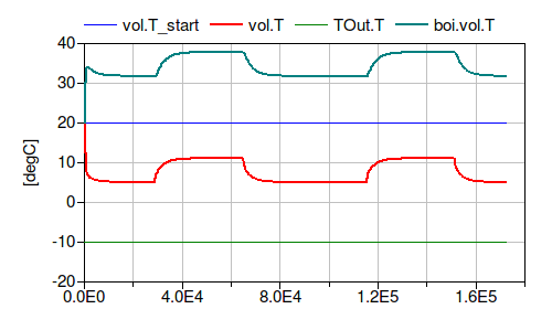
The figure shows that the room temperature is around 5°C when the internal heat gain is zero, i.e., it is at the average of the outside temperature and the room design temperature. Since the boiler control signal is 0.5, this indicates that the model is correct.
Parameters
| Type | Name | Default | Description |
|---|---|---|---|
| Modelica.Units.SI.HeatFlowRate | Q_flow_nominal | 20000 | Nominal heat flow rate of radiator |
| Modelica.Units.SI.Temperature | TRadSup_nominal | 273.15 + 50 | Radiator nominal supply water temperature |
| Modelica.Units.SI.Temperature | TRadRet_nominal | 273.15 + 40 | Radiator nominal return water temperature |
| Modelica.Units.SI.MassFlowRate | mRad_flow_nominal | Q_flow_nominal/4200/(TRadSup_nominal - TRadRet_nominal) | Radiator nominal mass flow rate |
| Modelica.Units.SI.Temperature | TBoiSup_nominal | 273.15 + 70 | Boiler nominal supply water temperature |
| Modelica.Units.SI.Temperature | TBoiRet_min | 273.15 + 60 | Boiler minimum return water temperature |
| Modelica.Units.SI.MassFlowRate | mBoi_flow_nominal | Q_flow_nominal/4200/(TBoiSup_nominal - TBoiRet_min) | Boiler nominal mass flow rate |
| Modelica.Units.SI.MassFlowRate | mRadVal_flow_nominal | Q_flow_nominal/4200/(TBoiSup_nominal - TRadRet_nominal) | Radiator nominal mass flow rate |
| Modelica.Units.SI.Volume | V | 6*10*3 | Room volume |
| Modelica.Units.SI.MassFlowRate | mA_flow_nominal | V*1.2*6/3600 | Nominal mass flow rate |
| Modelica.Units.SI.HeatFlowRate | QRooInt_flow | 4000 | Internal heat gains of the room |
Components
Contents
| Name | Description |
|---|---|
 MediumA MediumA | |
 MediumW MediumW | Medium model |
Revisions
-
October 14, 2026, by Michael Wetter:
Added prescribed temperature model for boiler heat loss.
This is for #4775. -
April 9, 2024, by Hongxiang Fu:
SpecifiednominalValuesDefineDefaultPressureCurve=truein the mover component to suppress a warning. This is for #3819. -
March 6, 2017, by Michael Wetter:
Added missing density to computation of air mass flow rate.
This is for #673. -
December 22, 2014 by Michael Wetter:
RemovedModelica.Fluid.Systemto address issue #311. -
March 1, 2013, by Michael Wetter:
Added nominal pressure drop for valves as this parameter no longer has a default value. -
January 27, 2012, by Michael Wetter:
First implementation.