
modelSystem2
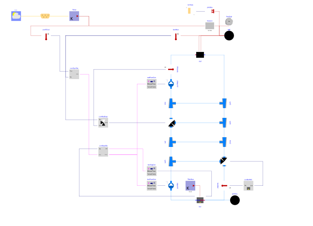
Extends from Buildings.Examples.Tutorial.CDL.BaseClasses.PartialOpenLoop (Partial model with open loop system).
Information
In this step, we added the control architecture. How the control is partitioned into various subcontrollers depends usually on the need to avoid communication over the network and on how control is distributed to different field controllers. Here, we used the four controllers indicated by the shaded background in the figure of Buildings.Examples.Tutorial.CDL. One controller switches the overall system on and off, one switches the boiler on and off, one tracks the supply water temperature to the room and one tracks the return water temperature that is fed to the boiler.
Implementation
This model was built as follows:
-
First, we determined what functionality should be implemented in which controller, and what the inputs and outputs of the controllers are. In this example, we used these controllers:
-
Boiler return water controller, with input being the return water temperature
TRetand output being the valve control signalyVal. -
Radiator loop temperature controller, with input being the measured supply water temperature
TSup, the measured room air temperatureTRooand output being the valve control signalyVal. -
System on/off controller, with inputs being the outdoor temperature
TOutand the room air temperatureTRoo, and output being the system on/off signalonSys. Note that how inputs and outputs are named can simplify usability. For example, we called the outputonSysso that a value oftrueis clearly understood as the system being on. If we had called ity, then it would not have been clear what a value oftruemeans. -
Equipment controller, with inputs being the system on/off command and the boiler temperature, and outputs being the pump on/off signal
onPumand the boiler on/off signalonBoi.
-
-
To organize our code, we created package that we called
Controls. -
Next, we added the open loop controller for the boiler return water temperature. This controller is implemented in Buildings.Examples.Tutorial.CDL.Controls.OpenLoopBoilerReturn. To implement it, we created a Modelica block, and added an input, using a Buildings.Controls.OBC.CDL.Interfaces.RealInput, called it
TRetfor the measured return water temperature, and a Buildings.Controls.OBC.CDL.Interfaces.RealOutput for the valve control signal, which we calledyVal.To output the valve control signal, which we set for now to a constant value of 1, we used an instance of Buildings.Controls.OBC.CDL.Reals.Sources.Constant, set its parameter to 1, and connected it to the output.
At this stage, because the control is open loop, we leave the input of the controller unconnected.
Looking at the Modelica file shows that we also added documentation in an
infosection, adefaultComponentName, as well as graphical elements so that it is easily distinguishable in a schematic diagram. We also added theunitanddisplayUnitattributes.In the next step of this tutorial, we will provide an actual implementation of the controller. To better distinguish the open loop controller from the closed loop controller, we color the icon of open loop controllers grey, and will change this color to white when we implement the actual control logic.
-
We did a similar process to add the other three open loop controllers. As before, we added all inputs and outputs, and set the outputs to a constant.
-
Lastly, we instantiated these four controllers in the system model. Because the pumps and the boiler take as a control input a real-valued signal, we used Buildings.Controls.OBC.CDL.Conversions.BooleanToReal to convert between the boolean-valued signal and the real-valued inputs of these components. Whether this conversion is part of the controller or done outside the controller is an individual design decision.
Exercise
Create a model, such as this model. To do so,
-
Implement all four open loop controllers.
-
Delete the constant control inputs, instantiate the open loop controllers, convert the signal as needed from
BooleantoReal, and connect the control inputs and outputs.
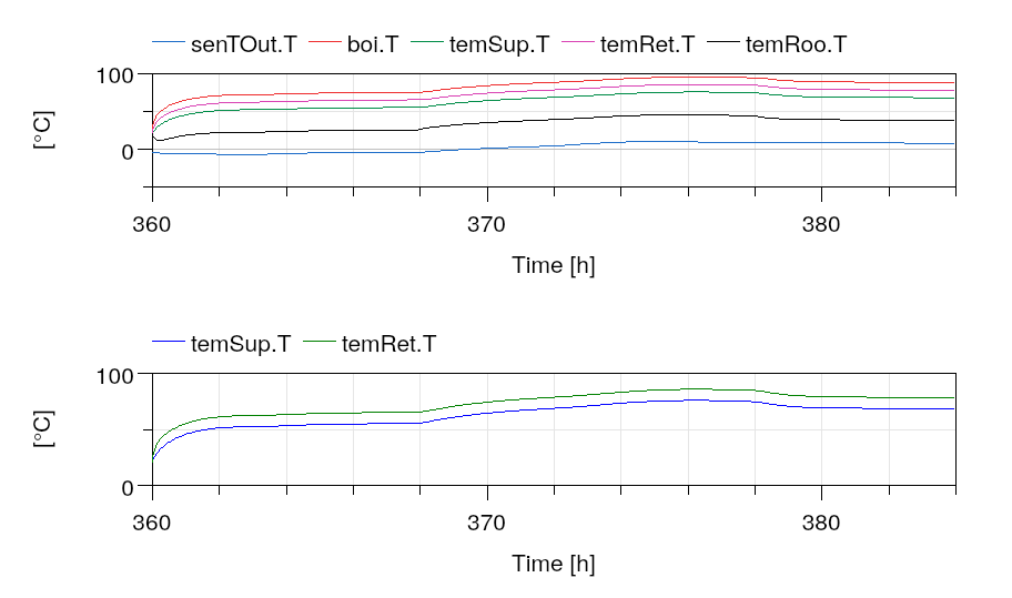
Simulate the system to verify that you get the response shown below. As we have not changed any of the control logic, simulating the system should give the same response as for Buildings.Examples.Tutorial.CDL.System1.
Parameters
| Type | Name | Default | Description |
|---|---|---|---|
| Modelica.Units.SI.HeatFlowRate | Q_flow_nominal (from PartialOpenLoop) | 20000 | Nominal heat flow rate of radiator |
| Modelica.Units.SI.Temperature | TRadSup_nominal (from PartialOpenLoop) | 273.15 + 50 | Radiator nominal supply water temperature |
| Modelica.Units.SI.Temperature | TRadRet_nominal (from PartialOpenLoop) | 273.15 + 40 | Radiator nominal return water temperature |
| Modelica.Units.SI.MassFlowRate | mRad_flow_nominal (from PartialOpenLoop) | Q_flow_nominal/4200/(TRadSup_nominal - TRadRet_nominal) | Radiator nominal mass flow rate |
| Modelica.Units.SI.Temperature | TBoiSup_nominal (from PartialOpenLoop) | 273.15 + 70 | Boiler nominal supply water temperature |
| Modelica.Units.SI.Temperature | TBoiRet_min (from PartialOpenLoop) | 273.15 + 60 | Boiler minimum return water temperature |
| Modelica.Units.SI.MassFlowRate | mBoi_flow_nominal (from PartialOpenLoop) | Q_flow_nominal/4200/(TBoiSup_nominal - TBoiRet_min) | Boiler nominal mass flow rate |
| Modelica.Units.SI.MassFlowRate | mRadVal_flow_nominal (from PartialOpenLoop) | Q_flow_nominal/4200/(TBoiSup_nominal - TRadRet_nominal) | Radiator nominal mass flow rate |
| Modelica.Units.SI.Volume | V (from PartialOpenLoop) | 6*10*3 | Room volume |
| Modelica.Units.SI.MassFlowRate | mA_flow_nominal (from PartialOpenLoop) | V*1.2*6/3600 | Nominal mass flow rate |
| Modelica.Units.SI.HeatFlowRate | QRooInt_flow (from PartialOpenLoop) | 4000 | Internal heat gains of the room |
Connectors
| Type | Name | Default | Description |
|---|---|---|---|
| BoundaryConditions.WeatherData.Bus | weaBus (from PartialOpenLoop) | Weather data bus |
Components
Revisions
-
February 18, 2020, by Michael Wetter:
First implementation.