modelWaterFlowControl
Extends from Modelica.Blocks.Icons.Block (Basic graphical layout of input/output block).
Information
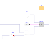
The model calculates the water mass flow rate that is determined by the internal controller. In CHPs that use this type of internal control the cooling water mass flow rate is controlled to optimize engine performance and heat recovery. In the main model of the CHP unit Buildings.Fluid.CHPs.ThermalElectricalFollowing, this optimum water mass flow rate is specified as the set point signal for the external pump controller.
Implementation
The mass flow rate is computed as a biquadratic function of the net power output of the system and the water inlet temperature. Note that this implementation is a truncated version of the empirical correlation proposed in Beausoleil-Morrison (2007) which includes terms of higher order (up to four).
References
Beausoleil-Morrison, Ian and Kelly, Nick, 2007. Specifications for modelling fuel cell and combustion-based residential cogeneration device within whole-building simulation programs, Section III. [Report]
Parameters
| Type | Name | Default | Description |
|---|---|---|---|
| Buildings.Fluid.CHPs.Data.Generic | per | Performance data |
Connectors
| Type | Name | Default | Description |
|---|---|---|---|
| Buildings.Fluid.CHPs.BaseClasses.Interfaces.ModeTypeInput | opeMod | Operation mode | |
| Buildings.Controls.OBC.CDL.Interfaces.RealInput | PEle | Electric power | |
| Buildings.Controls.OBC.CDL.Interfaces.RealInput | TWatIn | Water inlet temperature | |
| Buildings.Controls.OBC.CDL.Interfaces.RealOutput | mWatSet_flow | Water mass flow rate set point |
Revisions
-
June 18, 2019, by Tea Zakula:
First implementation.