modelThermalElectricalFollowing
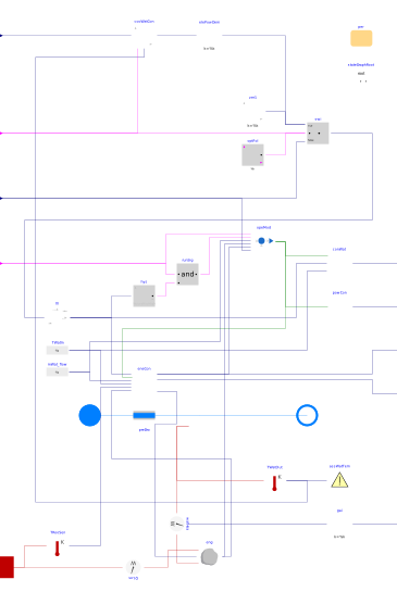
Extends from Buildings.Fluid.Interfaces.TwoPortHeatMassExchanger (Partial model transporting one fluid stream with storing mass or energy).
Information
This model for combined heat and power device uses empirical data contained within a "performance map" to represent device-specific performance characteristics coupled with thermally massive elements to characterize the device's dynamic thermal performance. It was developed based on the specification described in Beausoleil-Morrison (2007).
Model applicability
The model is primarily intended to predict the energy performance of combustion-based cogeneration devices, such as internal combustion engine and Stirling engine units. However, the general model specification makes it applicable to any device simultaneously producing heat and power from which heat is recovered as hot water, as long as recalibration is undertaken. Fuel cell based micro-cogeneration technology is outside of the modeling scope.
The parameters required to define the governing equations can be determined from bench testing with only non intrusive measurements (e.g. fuel flow rate, cooling water flow rates and temperature, electrical production). The ability to reuse and recalibrate the component models or sub-models ensures that they are applicable to future generations of cogeneration devices.
Model topology
Three control volumes are used to model the cogeneration unit dynamic thermal characteristics.
- The energy conversion control volume represents the engine working fluid, combustion gases and engine alternator. It feeds information from the engine unit performance map into the thermal model, see Buildings.Fluid.CHPs.BaseClasses.EnergyConversion.
- The thermal mass control volume represents the aggregated thermal capacitance associated with the engine block and the majority of the heat exchanger shells, see Buildings.Fluid.CHPs.BaseClasses.EngineTemperature.
- The cooling water control volume represents the cooling water flowing through the device and the elements of the heat exchanger in immediate thermal contact.
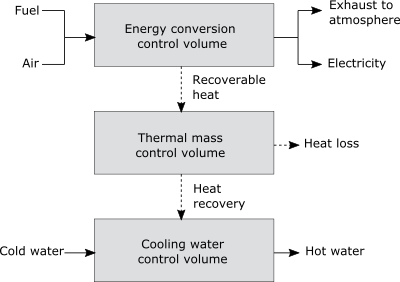
Depending on the current mode, control signals and plant boundary conditions, the CHP unit switches between six possible operating modes: off mode, stand-by mode, pump-on mode, warm-up mode, normal operation mode, cool-down mode. The mode switch control is implemented in Buildings.Fluid.CHPs.BaseClasses.Controller.
References
Beausoleil-Morrison, Ian and Kelly, Nick, 2007. Specifications for modelling fuel cell and combustion-based residential cogeneration device within whole-building simulation programs, Section III. [Report]
Parameters
| Type | Name | Default | Description |
|---|---|---|---|
| Boolean | homotopyInitialization (from TwoPortHeatMassExchanger) | true | = true, use homotopy method |
| Buildings.Fluid.CHPs.Data.Generic | per | CHP unit performance data | |
| Boolean | switchThermalElectricalFollowing | true | Set to true for switching between thermal and electrical following, to false for electrical following only |
| Modelica.Units.SI.Temperature | TEngIni | Medium.T_default | Initial engine temperature |
| Assumptions | |||
| Boolean | allowFlowReversal (from PartialTwoPort) | true | = false to simplify equations, assuming, but not enforcing, no flow reversal |
| Nominal condition | |||
| Modelica.Units.SI.MassFlowRate | m_flow_nominal (from PartialTwoPortInterface) | Nominal mass flow rate | |
| Modelica.Units.SI.PressureDifference | dp_nominal (from TwoPortFlowResistanceParameters) | Pressure difference | |
| Advanced | |||
| Modelica.Units.SI.MassFlowRate | m_flow_small (from PartialTwoPortInterface) | 1E-4*abs(m_flow_nominal) | Small mass flow rate for regularization of zero flow |
| Advanced › Diagnostics | |||
| Boolean | show_T (from PartialTwoPortInterface) | false | = true, if actual temperature at port is computed |
| Flow resistance | |||
| Boolean | computeFlowResistance (from TwoPortFlowResistanceParameters) | true | =true, compute flow resistance. Set to false to assume no friction |
| Boolean | from_dp (from TwoPortFlowResistanceParameters) | false | = true, use m_flow = f(dp) else dp = f(m_flow) |
| Real | n (from TwoPortFlowResistanceParameters) | 2 | Flow exponent, n=1 for laminar, n=2 for turbulent |
| Boolean | linearizeFlowResistance (from TwoPortFlowResistanceParameters) | false | = true, use linear relation between m_flow and dp for any flow rate |
| Real | deltaM (from TwoPortFlowResistanceParameters) | 0.1 | Fraction of nominal flow rate where flow transitions to laminar |
| Dynamics › Nominal condition | |||
| Modelica.Units.SI.Time | tau (from TwoPortHeatMassExchanger) | 30 | Time constant at nominal flow (if energyDynamics <> SteadyState) |
| Dynamics › Conservation equations | |||
| Modelica.Fluid.Types.Dynamics | energyDynamics (from TwoPortHeatMassExchanger) | Modelica.Fluid.Types.Dynamics.DynamicFreeInitial | Type of energy balance: dynamic (3 initialization options) or steady state |
| Initialization | |||
| Medium.AbsolutePressure | p_start (from TwoPortHeatMassExchanger) | Medium.p_default | Start value of pressure |
| Medium.Temperature | T_start (from TwoPortHeatMassExchanger) | Medium.T_default | Start value of temperature |
| Medium.MassFraction[Medium.nX] | X_start (from TwoPortHeatMassExchanger) | Medium.X_default | Start value of mass fractions m_i/m |
| Medium.ExtraProperty[Medium.nC] | C_start (from TwoPortHeatMassExchanger) | fill(0, Medium.nC) | Start value of trace substances |
| Dynamics | |||
| Modelica.Units.SI.Time | waitTime | 60 | Wait time before transition from pump-on mode fires |
| Cooling water outlet temperature controller | |||
| Controls.OBC.CDL.Types.SimpleController | watOutCon | Buildings.Controls.OBC.CDL.Types.SimpleController.PI | Type of controller |
| Real | k | 1 | Gain of controller |
| Modelica.Units.SI.Time | Ti | 0.5 | Time constant of integrator block |
| Modelica.Units.SI.Time | Td | 0.1 | Time constant of derivative block |
Connectors
| Type | Name | Default | Description |
|---|---|---|---|
| Modelica.Fluid.Interfaces.FluidPort_a | port_a (from PartialTwoPort) | Fluid connector a (positive design flow direction is from port_a to port_b) | |
| Modelica.Fluid.Interfaces.FluidPort_b | port_b (from PartialTwoPort) | Fluid connector b (positive design flow direction is from port_a to port_b) | |
| Buildings.Controls.OBC.CDL.Interfaces.RealInput | TWatOutSet | Water outlet set point temperature, which is input signal for thermal following | |
| Buildings.Controls.OBC.CDL.Interfaces.BooleanInput | theFol | Enable thermal following, false if electrical following | |
| Buildings.Controls.OBC.CDL.Interfaces.RealInput | PEleDem | Electric power demand | |
| Buildings.Controls.OBC.CDL.Interfaces.BooleanInput | avaSig | True when the plant is available | |
| Modelica.Thermal.HeatTransfer.Interfaces.HeatPort_a | TRoo | Heat port for room temperature | |
| Buildings.Controls.OBC.CDL.Interfaces.RealOutput | mWatSet_flow | Water mass flow rate set point based on internal control | |
| Buildings.Controls.OBC.CDL.Interfaces.RealOutput | PCon | Power consumption during stand-by and cool-down modes | |
| Buildings.Controls.OBC.CDL.Interfaces.RealOutput | PEleNet | Electric power generation | |
| Buildings.Controls.OBC.CDL.Interfaces.RealOutput | mFue_flow | Fuel mass flow rate | |
| Buildings.Controls.OBC.CDL.Interfaces.RealOutput | QWat_flow | Heat transfer rate to the water control volume |
Components
| Type | Name | Default | Description |
|---|---|---|---|
| Modelica.Units.SI.MassFlowRate | m_flow (from PartialTwoPortInterface) | port_a.m_flow | Mass flow rate from port_a to port_b (m_flow > 0 is design flow direction) |
| Modelica.Units.SI.PressureDifference | dp (from PartialTwoPortInterface) | port_a.p - port_b.p | Pressure difference between port_a and port_b |
| Medium.ThermodynamicState | sta_a (from PartialTwoPortInterface) | if allowFlowReversal then Medium.setState_phX(port_a.p, noEvent(actualStream(port_a.h_outflow)), noEvent(actualStream(port_a.Xi_outflow))) else Medium.setState_phX(port_a.p, noEvent(inStream(port_a.h_outflow)), noEvent(inStream(port_a.Xi_outflow))) | Medium properties in port_a |
| Medium.ThermodynamicState | sta_b (from PartialTwoPortInterface) | if allowFlowReversal then Medium.setState_phX(port_b.p, noEvent(actualStream(port_b.h_outflow)), noEvent(actualStream(port_b.Xi_outflow))) else Medium.setState_phX(port_b.p, noEvent(port_b.h_outflow), noEvent(port_b.Xi_outflow)) | Medium properties in port_b |
| Buildings.Fluid.MixingVolumes.MixingVolume | vol (from TwoPortHeatMassExchanger) | ||
| Buildings.Fluid.FixedResistances.PressureDrop | preDro (from TwoPortHeatMassExchanger) | Flow resistance | |
| Buildings.Fluid.CHPs.BaseClasses.EnergyConversion | eneCon | Energy conversion | |
| Buildings.Fluid.CHPs.BaseClasses.EngineTemperature | eng | Engine control volume | |
| Buildings.Fluid.CHPs.BaseClasses.Controller | opeMod | Current operation mode | |
| Buildings.Controls.OBC.CDL.Logical.And | runSig | Run if avaFlag and PEleDem non zero | |
| Buildings.Controls.OBC.CDL.Reals.Hysteresis | hys | Determine if demand larger than zero | |
| Buildings.Fluid.CHPs.BaseClasses.FilterPower | fil | Power after applied constraints | |
| Buildings.Fluid.CHPs.BaseClasses.WaterFlowControl | conWat | Internal controller for water mass flow rate | |
| Modelica.Blocks.Sources.RealExpression | mWat_flow | Water mass flow rate | |
| Modelica.Blocks.Sources.RealExpression | TWatIn | Water inlet temperature | |
| Buildings.Fluid.CHPs.BaseClasses.AssertWaterTemperature | assWatTem | Assert if water temperature is outside boundaries | |
| Modelica.Thermal.HeatTransfer.Sensors.TemperatureSensor | TWatOut | Water outlet temperature | |
| Modelica.Thermal.HeatTransfer.Sensors.HeatFlowSensor | watHea | Heat transfer from the water control volume | |
| Buildings.Fluid.CHPs.BaseClasses.PowerConsumption | powCon | Power consumption during stand-by and cool-down modes | |
| Modelica.Thermal.HeatTransfer.Sensors.HeatFlowSensor | QLos | Heat transfer to the surrounding | |
| Buildings.Controls.OBC.CDL.Reals.PIDWithReset | cooWatCon | Cooling water outlet controller | |
| Buildings.Controls.OBC.CDL.Reals.MultiplyByParameter | elePowDem | Electric power demand if thermal following | |
| Buildings.Controls.OBC.CDL.Reals.Switch | swi | Switch between thermal and electrical following | |
| Buildings.Controls.OBC.CDL.Logical.Sources.Constant | optFol | Feed false to switch block if no optional following | |
| Buildings.Controls.OBC.CDL.Reals.Sources.Constant | zer1 | Constant zero | |
| Buildings.Controls.OBC.CDL.Reals.MultiplyByParameter | gai | Heat transfer to the water control volume | |
| Modelica.StateGraph.StateGraphRoot | stateGraphRoot | ||
| Modelica.Thermal.HeatTransfer.Sensors.TemperatureSensor | TRooSen | Room temperature |
Revisions
-
April 30, 2021, by Michael Wetter:
Reformulated replaceable class to avoid access of components that are not in the constraining type.
This is for issue #2471. -
April 8, 2020, by Antoine Gautier:
Refactored implementation. -
February 14, 2020, by Jianjun Hu:
Added documentation. -
June 1, 2019, by Tea Zakula:
First implementation.