modelUTube
Extends from Buildings.Fluid.Interfaces.PartialTwoPortInterface (Partial model with two ports and declaration of quantities that are used by many models), Buildings.Fluid.Interfaces.TwoPortFlowResistanceParameters (Parameters for flow resistance for models with two ports), Buildings.Fluid.Interfaces.LumpedVolumeDeclarations (Declarations for lumped volumes).
Information
Model of a single U-tube borehole heat exchanger. The borehole heat exchanger is vertically discretized into nseg elements of height h=hBor⁄nseg. Each segment contains a model for the heat transfer in the borehole, for heat transfer in the soil and for the far-field boundary condition.
The heat transfer in the borehole is computed using a convective heat transfer coefficient that depends on the fluid velocity, a heat resistance between the two pipes, and a heat resistance between the pipes and the circumference of the borehole. The heat capacity of the fluid, and the heat capacity of the grout, is taken into account. The thermal resistance and capacity network inside the borehole is computed according to Bauer et al., (2011).
The heat transfer in the soil is computed using transient heat conduction in cylindrical coordinates for the spatial domain rbor ≤ r ≤ rext. In the radial direction, the spatial domain is discretized into nhor segments with uniform material properties. Thermal properties can be specified separately for each horizontal layer.
The far-field temperature, i.e., the temperature at the radius rext, is computed using a power-series solution to a line-source heat transfer problem. This temperature boundary condition is updated every tsample seconds.
The initial far-field temperature Text,start, which is the temperature of the soil at a radius rext, is computed as a function of the depth z > 0. For a depth between 0 ≤ z ≤ z0, the temperature is set to Text,0,start. The value of z0 is a parameter with a default of 10 meters. However, there is large variability in the depth where the undisturbed soil temperature starts. For a depth of z0 ≤ z ≤ hbor, the temperature is computed as
Tiext,start = Text,0,start + (zi - z0) dT ⁄ dz
with i ∈ {1, ..., nver}, where the temperature gradient dT ⁄ dz ≥ 0 is a parameter. As with z0, there is large variability in dT ⁄ dz ≥ 0. The default value is set to 1 Kelvin per 100 meters. For the temperature of the grout, the same equations are applied, with Text,0,start replaced with Tfil,0,start, and Tiext,start replaced with Tifil,start. The default setting uses the same temperature for the soil and the filling material.
Assumptions and limitations
The vertical heat flow is assumed to be zero and hence there is no heat flow from the ground surface to the soil that could be used to regenerate the soil temperature.
There is no ground water flow.
Implementation
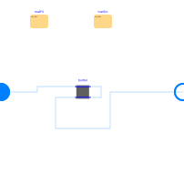
Each horizontal layer is modeled using an instance of Buildings.HeatExchangers.Fluid.Boreholes.BaseClasses.BoreholeSegment. This model is composed of the model Buildings.Fluid.Geothermal.Boreholes.BaseClasses.HexInternalElement which computes the heat transfer in the pipes and the borehole filling, of the model Buildings.HeatTransfer.Conduction.SingleLayerCylinder which computes the heat transfer in the soil, and of the model Buildings.Fluid.Geothermal.Boreholes.BaseClasses.SingleUTubeBoundaryCondition which computes the far-field temperature boundary condition. The thermal resistor and capacitor network is computed in Buildings.Fluid.Geothermal.Boreholes.BaseClasses.singleUTubeResistances.
References
D. Bauer, W. Heidemann, H. Müller-Steinhagen, and H.-J. G. Diersch. Thermal resistance and capacity models for borehole heat exchangers . International Journal Of Energy Research, 35:312–320, 2011.
Parameters
| Type | Name | Default | Description |
|---|---|---|---|
| Boolean | homotopyInitialization | true | = true, use homotopy method |
| Modelica.Units.SI.Radius | rBor | 0.1 | Radius of the borehole |
| Assumptions | |||
| Boolean | allowFlowReversal (from PartialTwoPort) | true | = false to simplify equations, assuming, but not enforcing, no flow reversal |
| Nominal condition | |||
| Modelica.Units.SI.MassFlowRate | m_flow_nominal (from PartialTwoPortInterface) | Nominal mass flow rate | |
| Modelica.Units.SI.PressureDifference | dp_nominal (from TwoPortFlowResistanceParameters) | Pressure difference | |
| Advanced | |||
| Modelica.Units.SI.MassFlowRate | m_flow_small (from PartialTwoPortInterface) | 1E-4*abs(m_flow_nominal) | Small mass flow rate for regularization of zero flow |
| Advanced › Diagnostics | |||
| Boolean | show_T (from PartialTwoPortInterface) | false | = true, if actual temperature at port is computed |
| Flow resistance | |||
| Boolean | computeFlowResistance (from TwoPortFlowResistanceParameters) | true | =true, compute flow resistance. Set to false to assume no friction |
| Boolean | from_dp (from TwoPortFlowResistanceParameters) | false | = true, use m_flow = f(dp) else dp = f(m_flow) |
| Real | n (from TwoPortFlowResistanceParameters) | 2 | Flow exponent, n=1 for laminar, n=2 for turbulent |
| Boolean | linearizeFlowResistance (from TwoPortFlowResistanceParameters) | false | = true, use linear relation between m_flow and dp for any flow rate |
| Real | deltaM (from TwoPortFlowResistanceParameters) | 0.1 | Fraction of nominal flow rate where flow transitions to laminar |
| Dynamics › Conservation equations | |||
| Modelica.Fluid.Types.Dynamics | energyDynamics (from LumpedVolumeDeclarations) | Modelica.Fluid.Types.Dynamics.DynamicFreeInitial | Type of energy balance: dynamic (3 initialization options) or steady state |
| Modelica.Fluid.Types.Dynamics | substanceDynamics (from LumpedVolumeDeclarations) | energyDynamics | Type of independent mass fraction balance: dynamic (3 initialization options) or steady state |
| Modelica.Fluid.Types.Dynamics | traceDynamics (from LumpedVolumeDeclarations) | energyDynamics | Type of trace substance balance: dynamic (3 initialization options) or steady state |
| Advanced › Dynamics | |||
| Modelica.Fluid.Types.Dynamics | massDynamics (from LumpedVolumeDeclarations) | energyDynamics | Type of mass balance: dynamic (3 initialization options) or steady state, must be steady state if energyDynamics is steady state |
| Initialization | |||
| Medium.AbsolutePressure | p_start (from LumpedVolumeDeclarations) | Medium.p_default | Start value of pressure |
| Medium.Temperature | T_start (from LumpedVolumeDeclarations) | Medium.T_default | Start value of temperature |
| Medium.MassFraction[Medium.nX] | X_start (from LumpedVolumeDeclarations) | Medium.X_default | Start value of mass fractions m_i/m |
| Medium.ExtraProperty[Medium.nC] | C_start (from LumpedVolumeDeclarations) | fill(0, Medium.nC) | Start value of trace substances |
| Medium.ExtraProperty[Medium.nC] | C_nominal (from LumpedVolumeDeclarations) | fill(1E-2, Medium.nC) | Nominal value of trace substances. (Set to typical order of magnitude.) |
| Dynamics | |||
| Real | mSenFac (from LumpedVolumeDeclarations) | 1 | Factor for scaling the sensible thermal mass of the volume |
| Soil | |||
| Buildings.HeatTransfer.Data.Soil.Generic | matSoi | Thermal properties of soil | |
| Modelica.Units.SI.Radius | rExt | 3 | Radius of the soil used for the external boundary condition |
| Integer | nHor | 10 | Number of state variables in each horizontal layer of the soil |
| Modelica.Units.SI.Time | samplePeriod | Sample period for the external boundary condition | |
| Borehole | |||
| Buildings.HeatTransfer.Data.BoreholeFillings.Generic | matFil | Thermal properties of the filling material | |
| Modelica.Units.SI.Height | hBor | Total height of the borehole | |
| Integer | nVer | 10 | Number of segments used for discretization in the vertical direction |
| Modelica.Units.SI.Length | xC | 0.05 | Shank spacing, defined as the distance between the center of a pipe and the center of the borehole |
| Real | B0 | 17.44 | Shape coefficient for grout resistance |
| Real | B1 | -0.605 | Shape coefficient for grout resistance |
| Tubes | |||
| Modelica.Units.SI.Radius | rTub | 0.02 | Radius of the tubes |
| Modelica.Units.SI.ThermalConductivity | kTub | 0.5 | Thermal conductivity of the tube |
| Modelica.Units.SI.Length | eTub | 0.002 | Thickness of a tube |
| Initial temperature › Soil | |||
| Modelica.Units.SI.Temperature | TExt0_start | 283.15 | Initial far field temperature |
| Modelica.Units.SI.Temperature[nVer] | TExt_start | {if z[i] >= z0 then TExt0_start + (z[i] - z0)*dT_dz else TExt0_start for i in 1:nVer} | Temperature of the undisturbed ground |
| Initial temperature › Filling material | |||
| Modelica.Units.SI.Temperature | TFil0_start | TExt0_start | Initial temperature of the filling material for h = 0...z0 |
| Modelica.Units.SI.Temperature[nVer] | TFil_start | TExt_start | Temperature of the undisturbed ground |
| Initial temperature › Temperature profile | |||
| Modelica.Units.SI.Height | z0 | 10 | Depth below which the temperature gradient starts |
| Real | dT_dz | 0.01 | Vertical temperature gradient of the undisturbed soil for h below z0 |
Connectors
| Type | Name | Default | Description |
|---|---|---|---|
| Modelica.Fluid.Interfaces.FluidPort_a | port_a (from PartialTwoPort) | Fluid connector a (positive design flow direction is from port_a to port_b) | |
| Modelica.Fluid.Interfaces.FluidPort_b | port_b (from PartialTwoPort) | Fluid connector b (positive design flow direction is from port_a to port_b) |
Components
| Type | Name | Default | Description |
|---|---|---|---|
| Modelica.Units.SI.MassFlowRate | m_flow (from PartialTwoPortInterface) | port_a.m_flow | Mass flow rate from port_a to port_b (m_flow > 0 is design flow direction) |
| Modelica.Units.SI.PressureDifference | dp (from PartialTwoPortInterface) | port_a.p - port_b.p | Pressure difference between port_a and port_b |
| Medium.ThermodynamicState | sta_a (from PartialTwoPortInterface) | if allowFlowReversal then Medium.setState_phX(port_a.p, noEvent(actualStream(port_a.h_outflow)), noEvent(actualStream(port_a.Xi_outflow))) else Medium.setState_phX(port_a.p, noEvent(inStream(port_a.h_outflow)), noEvent(inStream(port_a.Xi_outflow))) | Medium properties in port_a |
| Medium.ThermodynamicState | sta_b (from PartialTwoPortInterface) | if allowFlowReversal then Medium.setState_phX(port_b.p, noEvent(actualStream(port_b.h_outflow)), noEvent(actualStream(port_b.Xi_outflow))) else Medium.setState_phX(port_b.p, noEvent(port_b.h_outflow), noEvent(port_b.Xi_outflow)) | Medium properties in port_b |
| Buildings.Fluid.Geothermal.Boreholes.BaseClasses.BoreholeSegment[nVer] | borHol | Discretized borehole segments | |
| Modelica.Units.SI.Temperature[nVer] | Tdown | Medium temperature in pipe 1 | |
| Modelica.Units.SI.Temperature[nVer] | Tup | Medium temperature in pipe 2 |
Revisions
-
March 7, 2022, by Michael Wetter:
Setfinal massDynamics=energyDynamics.
This is for #1542. -
April 14, 2020, by Michael Wetter:
ChangedhomotopyInitializationto a constant.
This is for IBPSA, #1341. -
December 23, 2015, by Michael Wetter:
Updated documentation and added section about model assumptions and limitations. -
October 8, 2013, by Michael Wetter:
Removed parametershow_V_flow. -
September 27, 2013, by Michael Wetter:
Added missingeachin propagation of material properties. -
August 2011, by Pierre Vigouroux:
First implementation.