modelWetCoilDryWetRegime

Information
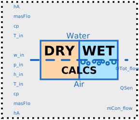
This model implements the switching algorithm for the dry and wet regime.
The switching criteria for (counter-flow) cooling coil modes are as follows.
R1: If the coil surface temperature at the air inlet is lower than the dew-point temperature at the inlet to the coil, then the cooling coil surface is fully-wet.
R2: If the surface temperature at the air outlet section is higher than the dew-point temperature of the air at the inlet, then the cooling coil surface is fully-dry.
At each point of a simulation time step, the fuzzy-modeling approach determines the weights for R1 and R2 respectively (namely μFW and μFD) from the dew-point and coil surface temperatures.
It calculates total and sensible heat transfer rates according to the weights as follows.
Q̇tot=μFD Q̇tot,FD+μFW Qtot,FW
Q̇sen=μFD Q̇sen,FD+μFW Qsen,FW
The fuzzy-modeling ensures μFW + μFD = 1, μFW >=0 and μFD >=0, which means the fuzzy model outcomes of Q̇sen and Q̇tot are always convex combinations of heat transfer rates for fully-dry and fully-wet modes and therefore are always bounded by them.
The modeling approach also results in n-th order differentiable model depending on the selection of the underlying membership functions. This cooling coil model is once continuously differentiable at the mode switches.
Parameters
| Type | Name | Default | Description |
|---|---|---|---|
| Nominal condition | |||
| Modelica.Units.SI.MassFlowRate | mWat_flow_nominal | Nominal mass flow rate for water | |
| Modelica.Units.SI.MassFlowRate | mAir_flow_nominal | Nominal mass flow rate for air | |
Connectors
| Type | Name | Default | Description |
|---|---|---|---|
| Modelica.Blocks.Interfaces.RealInput | UAWat | Product of heat transfer coefficient times area for water side | |
| Modelica.Blocks.Interfaces.RealInput | mWat_flow | Mass flow rate for water | |
| Modelica.Blocks.Interfaces.RealInput | cpWat | Inlet water temperature | |
| Modelica.Blocks.Interfaces.RealInput | TWatIn | Inlet water temperature | |
| Modelica.Blocks.Interfaces.RealInput | UAAir | Product of heat transfer coefficient times area for air side | |
| Modelica.Blocks.Interfaces.RealInput | mAir_flow | Mass flow rate for air | |
| Modelica.Blocks.Interfaces.RealInput | cpAir | Inlet specific heat capacity (at constant pressure) | |
| Modelica.Blocks.Interfaces.RealInput | TAirIn | Inlet air temperature | |
| Modelica.Blocks.Interfaces.RealInput | hAirIn | Inlet air enthalpy | |
| Modelica.Blocks.Interfaces.RealInput | pAir | Inlet air absolute pressure | |
| Modelica.Blocks.Interfaces.RealInput | X_wAirIn | Mass fraction of water in inlet air (kg water/kg total air) | |
| Modelica.Blocks.Interfaces.RealOutput | QTot_flow | Total heat transfer from water into air, negative for cooling | |
| Modelica.Blocks.Interfaces.RealOutput | QSen_flow | Sensible heat transfer from water into air, negative for cooling | |
| Modelica.Blocks.Interfaces.RealOutput | mCon_flow | Mass flow of the condensate, negative for dehumidification |
Components
| Type | Name | Default | Description |
|---|---|---|---|
| Real | Qfac | Smoothing factor to prevent division-by-zero | |
| Buildings.Fluid.Types.HeatExchangerFlowRegime | cfg | Buildings.Fluid.Types.HeatExchangerFlowRegime.CounterFlow | Heat exchanger configuration |
| Modelica.Units.SI.HeatFlowRate | QLat_flow | Latent heat transfer rate | |
| Buildings.Fluid.HeatExchangers.BaseClasses.WetCoilDryRegime | fullyDry | Fully-dry coil model | |
| Buildings.Fluid.HeatExchangers.BaseClasses.WetCoilWetRegime | fullyWet | Fully-wet coil model | |
| Real | dryFra | Dry fraction, 0.3 means condensation occurs at 30% heat exchange length from air inlet |
Revisions
-
Jan 21, 2021, by Donghun Kim:
First implementation.